
Orifice (diaphragm) calculation
1. Introduction
2. Pressure drop through an orifice
3. Interactive Orifice Calculator & Sizing Tool
Top 5 Most Popular
1. Introduction
Orifices are often used in fluid mechanics to limit mechanically the flow. It is important to be able to size them.
The restriction orifice mentioned here is a thin perforated plate, also called diaphragm.
2. Pressure drop through an orifice
The following correlation is given by Gibson, it is reproduced in many books.
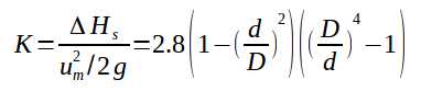
With :
\(K\) = Pressure drop coefficient (dimensionless)
\(D\) = Pipe internal diameter (m)
\(d\) = Orifice / diaphragm diameter (m)
\(u_m\) = Fluid velocity before diaphragm / upstream (m/s)
\(\Delta H_s\) = Singularity pressure drop head loss (m of fluid)
\(g\) = Acceleration due to gravity (\(9.80665 \text{ m/s}^2\))
The coefficient \(K\) can also be calculated thanks to the following graph :
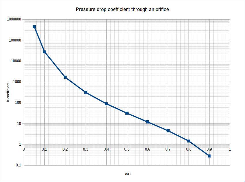
Source: Gibson et al., Hydraulics and its applications, 5th edition, Constable London, 1952
💡 Process Engineering Rules of Thumb & Design Limits
- Beta Ratio (\(\beta = d/D\)): Best practices recommend maintaining \(\beta\) between 0.20 and 0.70. Ratios below 0.20 lead to severe jet velocity, potential cavitation, severe noise, and extreme wear. Ratios above 0.70 yield minimal pressure differential.
- Liquid Line Velocity Limits: Keep upstream pipe velocity \(u_m \le 1.5 - 2.5\text{ m/s}\) (\(5 - 8\text{ ft/s}\)) to prevent upstream acoustic vibration. Orifice throat velocity should ideally be kept below \(10 - 15\text{ m/s}\) to prevent cavitation and erosion.
- Maximum Single-Stage Pressure Drop: For liquid systems, limit single-stage pressure drop to \(3.0\text{ bar}\) (\(45\text{ psi}\)). For higher pressure drops, use multi-stage restriction orifices to avoid cavitation choking.
- Applicability Limits: The Gibson correlation applies to sharp-edged thin diaphragms operating under fully turbulent flow conditions (\(Re_D > 10,000\)).