
Colebrook correlation (friction factor)
Question or remark ? Please contact us at contact@myengineeringtools.com
1. Introduction
2. Colebrook equation
3. Interactive Colebrook Calculator
4. Engineering Rules of Thumb & Material Roughness
1. Introduction
2. Colebrook equation
The Colebrook equation is a widely used empirical formula that is used to calculate the friction factor in turbulent flow of fluids in pipes. It relates the friction factor to the Reynolds number and the relative roughness of the pipe wall. The equation is commonly used in engineering and fluid mechanics to estimate the pressure drop in pipes.
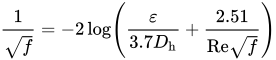
Note : log base 10
With :
f = Darcy friction factor
Dh = Hydraulic diameter (m)
Re = Reynolds number
ε = pipe roughness (m)
There are other equations that can be used to calculate the friction factor as well, such as the Darcy-Weisbach equation and the Hazen-Williams equation. These equations also relate the friction factor to the Reynolds number and the roughness of the pipe wall, but they use different empirical constants and assumptions. The choice of equation depends on the specific application and the available data.
Note that Colebrook equation is not explicit, thus it requires some iterations to solve it. To have a direct expression, with an acceptable accuracy, you can use Churchill equation.
3. Interactive Colebrook Calculator
4. Practical Plant Engineering Rules of Thumb
💡 Process Engineering Guidelines for Friction Factors:
- Flow Regimes: For \(\text{Re} < 2300\), flow is laminar and friction factor depends only on Reynolds number (\(f = 64/\text{Re}\)). For \(\text{Re} > 4000\), turbulent flow prevails and Colebrook correlation applies. The region \(2300 \le \text{Re} \le 4000\) is transitional and unstable.
- Darcy vs. Fanning Convention: Always confirm whether your pressure drop formula or chart uses Darcy (\(f_D\)) or Fanning (\(f_F\)) friction factor. Note that \(f_D = 4 \times f_F\). Mistaking one for the other causes a 400% calculation error in head loss!
- Aging Pipe Margin: New commercial steel pipes typically have \(\varepsilon \approx 0.045\text{ mm}\). However, in water and process service, corrosion and fouling increase surface roughness over time up to \(\varepsilon = 0.15 - 0.50\text{ mm}\). Always include a 15–20% design pressure drop allowance for pipe aging.
- Explicit Approximations: For fast spreadsheet calculation without iterative solvers, the Haaland or Swamee-Jain equations provide direct explicit friction factors within ±1.5% of the Colebrook equation.