
Water hammer : what it is, how to prevent it, how to calculate
the max pressure
Follow us on Twitter 
Question, remark ? Contact us at contact@myengineeringtools.com
1. Introduction
2. Consequences of a water hammer
3. Water hammer pressure rise calculation
4. Prevention of water hammer
5. Water hammer pressure rise online & Excel calculator
1. Introduction
What is the "water hammer" phenomenon ?
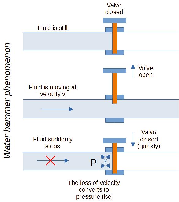
Water hammer, also known as hydraulic shock or surge, is a sudden pressure increase or shockwave that occurs within a fluid-carrying pipe system when there is a rapid change in flow velocity. It happens due to the inertia of the moving fluid and the compressibility of water. The phenomenon often results from abrupt valve closures (including check valves), pump starts and stops, or sudden changes in flow direction.
2. Consequences of a water hammer
When a flow is suddenly halted or redirected, the kinetic energy of the moving water transforms into pressure energy, causing pressure spikes that can damage pipes, valves, instruments, and other system components. The resulting shockwave travels back and forth through the piping system at the speed of sound in the liquid, creating a distinct metallic slamming or banging noise.
3. Water hammer pressure rise calculation
The pressure rise that will happen due to water hammer when there is a sudden stop of the flow (very quick valve or check valve closure for instance) can be calculated thanks to the Joukowsky equation [Hall]:
With :
\(\Delta P_h\) = increase of pressure due to water hammer (Pa)
\(\rho\) = fluid density (kg/m³)
\(c_s\) = velocity of sound in the fluid (m/s) = ~1439 m/s for water
(varies with temperature & pipe elasticity)
\(u\) = fluid velocity (m/s)
It's important to note that water hammer can have serious consequences, including pipe bursts, flange leaks, equipment damage, and complete system failures.
Note the formula above assumes that the velocity of the fluid will go to 0 (hence expressed with \(u\)). Other sources consider a difference in velocity (\(\Delta u\)) that could be useful for partial valve closures or sudden changes of flow direction.
Another formula is proposed when slow closure of a valve is happening:
With :
\(P_2\) = maximum peak pressure reached during water hammer
phenomena (Pa)
\(P_1\) = initial line pressure before closure (Pa)
\(\rho\) = fluid density (kg/m³)
\(u\) = fluid velocity (m/s)
\(L\) = upstream pipe length (m)
\(t\) = valve closure time (s)
This slow closure formula is approximate [Perry]; appropriate design safety margins must always be applied.
The boundary between sudden (instantaneous) closure and slow closure depends on the critical time \(t_c\):
If the closure time \(t \le t_c\), the closure is hydrodynamically instantaneous, and the full Joukowsky pressure surge applies regardless of how long the operator takes to turn the valve.
💡 Practical Plant Engineering Rules of Thumb & Safety Limits
- Maximum Velocity Limits: Design liquid lines to stay under 1.5 to 2.1 m/s (5 to 7 ft/s) for general service, and below 1.2 m/s (4 ft/s) on pump suction lines to prevent cavitational hydraulic shocks.
- Critical Closure Time (\(t_c\)): Always verify that valve closing times exceed \(t_c = \frac{2L}{c_s}\). Valve strokes shorter than \(t_c\) cause maximum Joukowsky pressure spikes regardless of nominal stroke time.
- Valve Closing Profiles: Utilize equal-percentage flow characteristics or two-speed valve actuators (closing 80% quickly and the final 20% slowly) to dramatically suppress pressure peak spikes.
- Check Valve Selection: Replace swing check valves with spring-assisted "silent" check valves on pump discharge headers to ensure the valve closes before fluid momentum reverses.
- Surge Absorbers: In long pipelines, position bladder-type surge tanks, air vessels, or relief valves immediately upstream of fast-acting shutoff valves.
4. Prevention of water hammer
The following design considerations can help to prevent water hammer from occurring:
- Respect recommended fluid velocities (please check those resources: max recommended velocity in pipe)
- Control and extend the speed at which valves close
- Install surge tanks that will help maintain flow momentum and absorb pressure shocks
- Employing air chambers, typically in the form of tee-fittings with air-filled chambers, can act as shock absorbers, reducing the shock's impact on the pipeline during sudden flow changes
- Choosing the right type of check valve. It's crucial to consider the type of check valve used in the system. Swing, tilting disc, or piston-style check valves, which rely on gravity and flow reversal to close, can contribute to water hammer by causing water to slam into the valve mechanism. Silent or spring-assisted check valves, equipped with internal springs, offer a quiet solution by closing before flow reversal occurs
- Install Steam Lines with a Gradual Slope: The water hammer effect in steam lines occurs from condensation accumulation and liquid slugging. Installing steam lines with a gradual slope toward condensate drain traps combats liquid accumulation
5. Water Hammer Pressure Rise Online & Excel Calculator
Interactive Water Hammer Sizing Tool
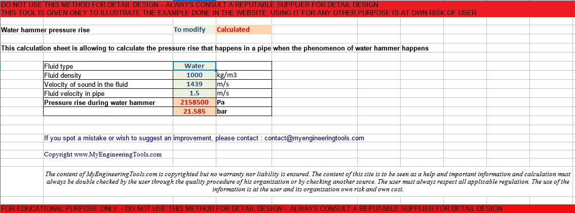
You can also access the downloadable Excel calculation spreadsheet to evaluate water hammer surge pressure in your piping design: Water Hammer Pressure Rise Excel Calculation Tool
Warning : this calculator is provided to illustrate the concepts mentioned in this webpage, it is not intended for detail design. It is not a commercial product, no guarantee is given on the results. Please consult a reputable designer for all detail design you may need.
Source & References
[Perry] Perry's Chemical Engineers' Handbook, 8th Edition, 2008, page 6-45