Pressure Safety Valve Basic Design guide - Gas & Steam
Flow (API 520)
Pressure Relief Valve Sizing & API Orifice Selection
1. Introduction and warning
1. Introduction and warning
This design guide aims the reader at understanding the basic concepts behind the design and sizing of pressure relief valves but not at designing a valve for operational purposes. It is based on published sources but should not be considered for the detail design and selection / ordering of a pressure safety valve. Indeed, pressure safety valves are of utmost importance for the safety of the process, as they are most often the last resort to avoid an explosion, their design must therefore be done only by reputable companies. Only after having clearly defined the application, the position of the valve...etc... with the valve supplier, can he advise properly the plant operator and finalize the design of the valve.
The calculation below are derived from API 520 and adapted from various sources. Those calculations are valid for a maximum allowable working pressure higher than 101325 Pa. Other types of services will require a different calculation code. API for example has other standards for low pressure valves. ASME or ISO have their own guidelines.
Note that this page is not discussing the choice and calculation of the design scenario, which is the process events leading to the maximum flow released through the valve. The required flow must be defined thanks to a risk analysis and process calculations.
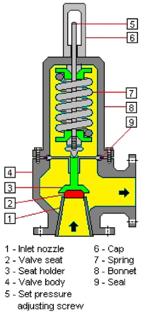
Figure 1 : Typical design of a pressure safety valve
2. API 520 relief valve sizing
How do you size a pressure safety valve?
2.1 Critical flow or subcritical flow
It is 1st necessary to determine how will be the flow in case of opening of the pressure relief valve. If the difference in between the pressure within the tank and pressure at the outlet of the valve is too important, the flow will be critical.
The critical pressure above which the flow becomes critical is calculated thanks to :
\[ \frac{P_c}{P_1} = \left[ \frac{2}{k+1} \right]^{\frac{k}{k-1}} \]
With :
Pc = critical pressure in kPa abs
P1 = upstream relieving pressure in kPa abs
P2 = downstream pressure in kPa abs
k = Cp/Cv
The following comparison must then be done to know if the flow will be sub-critical or critical and use the right formulae :
| P2 ≤ Pc | Critical flow |
| P2 > Pc | Sub-critical flow |
2.2 Critical flow Safety Valve sizing
If the flow has been found to be critical, the following formula can be used :
\[ A = 13160 \cdot \frac{W}{C \cdot Kd \cdot P_1 \cdot Kb \cdot Kc} \sqrt{\frac{T \cdot Z}{M}} \]
W = required flow through the valve in kg/h
Kd = coefficient of discharge
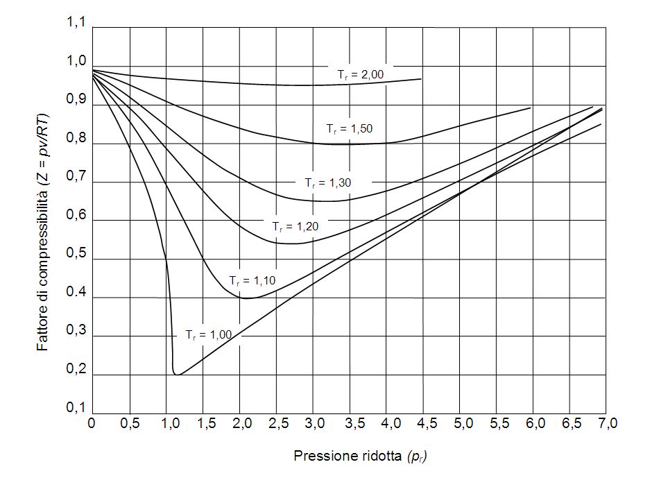
Z = compressibility factor of the gas at valve inlet conditions
M = molecular weight of the gas in kg/kmol
\[ C = 520 \cdot \sqrt{k \left( \frac{2}{k+1} \right)^{\frac{k+1}{k-1}}} \]
2.3 Sub-critical flow safety valve sizing
\[ A = \frac{17.9 \cdot W}{F2 \cdot Kd \cdot Kc} \cdot \sqrt{\frac{T \cdot Z}{M \cdot P_1 (P_1 - P_2)}} \]
\[ F2 = \sqrt{\left( \frac{k}{k-1} \right) \left( \frac{P_2}{P_1} \right)^{\frac{2}{k}} \left( \frac{1 - \left( \frac{P_2}{P_1} \right)^{\frac{k-1}{k}}}{1 - \frac{P_2}{P_1}} \right)} \]
2.4 Special case of steam
\[ A = \frac{190.4 \cdot W}{P_1 \cdot Kd \cdot Kb \cdot Kc \cdot K_N \cdot Ksh} \]
💡 Practical Plant Engineering Rules of Thumb & Safety Design Limits
- 3% Inlet Pressure Drop Rule: Non-recoverable pressure losses in the piping connecting the vessel nozzle to the PSV inlet flange must not exceed 3% of the set pressure. Exceeding 3% causes rapid opening/closing cycles ("chattering"), damaging valve seats and inducing heavy vibration.
- 10% Backpressure Limit for Conventional PSVs: Built-up backpressure on a conventional spring-loaded PSV alters the set pressure and reduces lift capacity. If variable backpressure exceeds 10% of set pressure, specify a Balanced Bellows PSV or Pilot-Operated PSV.
- Overpressure Allowances (API 520 / ASME VIII):
- Non-fire operational contingency: Max 10% overpressure above Set Pressure.
- Multiple valve installation: Max 16% overpressure.
- Fire emergency scenario: Max 21% overpressure.
- Discharge Piping Reaction Forces & Subsonic Velocity: Tailpipes discharging to atmosphere must be sized to ensure exit gas velocity remains below 0.75 Mach to prevent excessive momentum forces and acoustic fatigue on supporting structural steel.
3. Interactive Online PSV Sizing Calculator
4. Selection of Standard Relief Valves Orifice
Pressure safety valves symbols & API 526 Standard Designation
The sizes of discharge areas is actually standardized and manufacturers will propose sizes accordingly. The Engineer, after having calculated the required size with the calculation sequence above, needs to select a standard size offering a discharge area higher than the calculated value.
| Standard Letter / Designation | Orifice Area (in²) | Orifice Area (cm²) | Orifice Area (mm²) |
|---|---|---|---|
| D | 0.110 | 0.71 | 71.0 |
| E | 0.196 | 1.26 | 126.0 |
| F | 0.307 | 1.98 | 198.0 |
| G | 0.503 | 3.24 | 324.0 |
| H | 0.785 | 5.06 | 506.0 |
| J | 1.280 | 8.30 | 830.0 |
| K | 1.840 | 11.85 | 1185.0 |
| L | 2.850 | 18.40 | 1840.0 |
| M | 3.600 | 23.23 | 2323.0 |
| N | 4.340 | 28.00 | 2800.0 |
| P | 6.380 | 41.16 | 4116.0 |
| Q | 11.050 | 71.29 | 7129.0 |
| R | 16.000 | 103.22 | 10322.0 |
| T | 26.000 | 167.74 | 16774.0 |
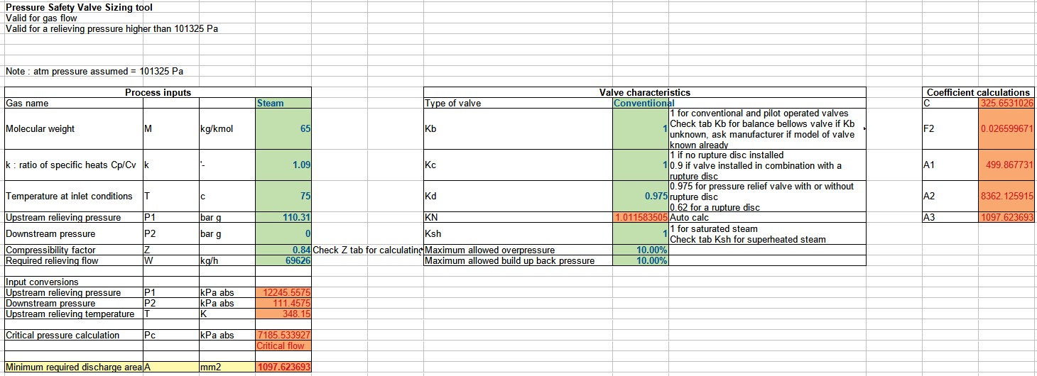
5. Pressure safety valve sizing calculation xls : Excel calculation tool
Note : the tool is for now only supporting gas flow in pressure :
Link to Excel calculation toolWARNING
www.powderprocess.net and www.myengineeringtools.com cannot be held responsible for the use of the explanations, calculation and calculation tools presented here, the use of the information is at the user and its organization own risk and cost.