Pressure Safety Valve Basic Design guide - Low pressure venting
Pressure Relief Valve sizing for atmospheric, low pressure tanks (pressure / vacuum)
1. Introduction and warning
2. Interactive Safety Valve Sizing Calculator (API 2000)
3. Theory & Governing Equations
4. Practical Selection & Overpressure Characteristics
1. Introduction and warning
This design guide aims the reader at understanding the basic concepts behind the design and sizing of pressure relief valves for low pressure venting but not at designing a valve for operational purposes. It is based on published sources but should not be considered for the detail design and selection / ordering of a pressure safety valve. Indeed, pressure safety valves are of utmost importance for the safety of the process, as they are most often the last resort to avoid an explosion or tank collapse, their design must therefore be done only by reputable companies. Only after having clearly defined the application, the position of the valve, etc., with the valve supplier, can he advise properly the plant operator and finalize the design of the valve.2. Interactive Low Pressure Relief Valve Calculator (API 2000)
Calculation Results
Click "Calculate Vent Capacity / Area" to compute results.
💡 Plant Engineering Rules of Thumb & Safety Limits
- Pressure Limits: Standard API 2000 low-pressure models strictly apply to set pressures below 15 psig (1.034 bar g). Exceeding this pressure transitions flow into compressible sonic choking regimes governed by API 520.
- Overpressure Margins: Direct weight-loaded or spring-loaded pallet vents require 100% overpressure above set pressure to reach full certified lift capacity. For tight tank design limits, pilot-operated valves reach rated capacity at 10% overpressure.
- Vacuum Protection: Vacuum vent lines must account for atmospheric condensation and potential freezing/icing at low ambient temperatures, which can freeze valve seats shut.
- Backpressure Limits: Atmospheric vents releasing directly to air have $P_2 = 1.013\text{ bar abs}$ ($14.696\text{ psia}$). Header discharge backpressure drastically reduces flow capacity due to smaller $\Delta P$ ratios.
3. Theory & Governing Equations
For low pressure tanks, the following formula derived from API 2000 5th Edition can be used (WARNING - This formula is not valid for gas at pressure > 1.034 barg and not valid for liquid, please refer to the high pressure PSV page):
With :
4. Practical Selection & Overpressure Characteristics
The actual flow through the valve is lower than the theoretical flow. This non-ideality is represented thanks to a coefficient of discharge of the valve, \(K\).
K = Actual flow / Theoretical flow
The coefficient K is defined by the manufacturer. API 2000 5th edition gives an example coefficient table:
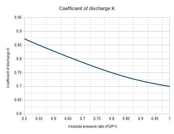
Figure 1 : Coefficient of discharge K of low pressure / vacuum safety valves
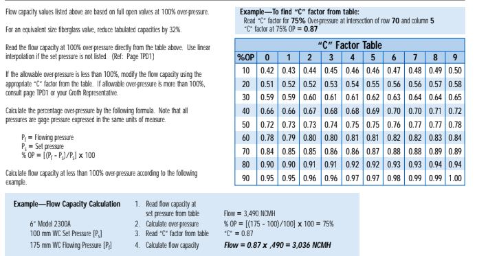
Depending on the technology of the valve chosen, either direct operated (weighted pallet valve) or pilot operated, an overpressure is required to reach the maximum flow. API 2000 provides the following graph to estimate the overpressure per type of valve. It is very important to consider, especially for direct acting valves that will only reach their rated capacity at 100% overpressure. The protected tank must therefore be able to hold this overpressure safely.

Figure 2 : Capacity / Overpressure characteristics of low pressure vents
Practical Valve Sizing
This kind of valve flow is highly dependent on the valve design and actual allowable overpressure. It is strongly recommended to refer to the manufacturer's flow capacity tables for a given valve model, calculated according to API 2000. An example table is shown below:
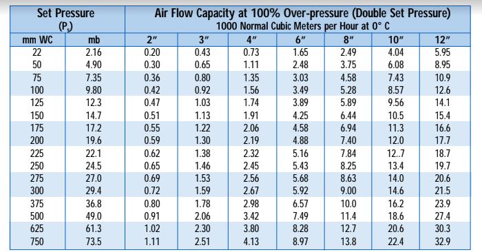
Once the valve is selected for the required flow application, the actual flow considering the overpressure must be determined. Another table with a corrective coefficient is then applied. If the acceptable overpressure differs from standard test benchmarks, the flow must be corrected accordingly.