
CSTR : Reaction Conversion
Follow us on Twitter 
Question, remark ? Contact us at contact@myengineeringtools.com
1. Reaction Conversion
2. Interactive CSTR Design & Rating Calculator
3. CSTR Reactor : Reaction Speed as a Function of Conversion
4. Conversion in Case of Multiple Reactions
5. Advanced Engineering Considerations for CSTR Conversion
6. Practical Design Example - First-Order Decomposition
7. Frequently Asked Questions
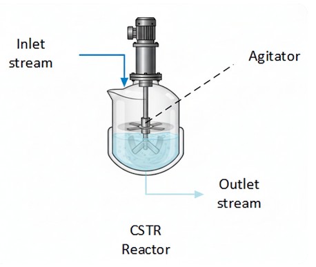
It can be interesting to define a conversion rate in order to express the reaction speed. The conversion is based on the limited reactant in a reaction. It is applied in this page to the CSTR reactor.
1. Reaction conversion
What is the conversion in a chemical reaction?
The reaction conversion is a measure of the progress of the reaction referring to the limiting reactant. The reaction will indeed not be able to go further once one of the reactant is consumed. The conversion rate of the reaction, based on the limiting reactant (named A hereafter), can then be defined as \(X_A\) by the following equation:
\[ F_{A,\text{out}} = F_{A,\text{in}} \cdot (1 + \nu_A \cdot X_A) \]
With:
\(F_{A,\text{out}}\) = material flowrate of the limiting reactant
A leaving the reactor (mol/s)
\(F_{A,\text{in}}\) = material flowrate of the limiting reactant A
entering the reactor (mol/s)
\(\nu_A\) = stoichiometric coefficient associated with the limiting
reactant A in the reaction considered. As we refer to a reactant,
\(\nu_A < 0\)
\(X_A\) = conversion rate relatively to the limiting reactant A
At \(t=0\) : \(X_A = 0\)
At \(t = \text{end of reaction}\) : \(X_A =
-1/\nu_A\)
CSTR Reactor Conversion & Sizing Calculator
Calculation Results
2. CSTR reactor : reaction speed as a function of
conversion
The mass balance in a CSTR reactor, perfectly stirred and isothermal allows to show that the reaction speed of a reactant A is:
\[ r_A = \frac{Q_{\text{in}} [A]_{\text{in}} - Q_{\text{out}} [A]_{\text{out}}}{V \cdot \nu_A} = \frac{F_{A,\text{in}} - F_{A,\text{out}}}{V \cdot \nu_A} \]
For the limiting reactant A, the flow of material leaving the reactor is:
\[ F_{A,\text{out}} = F_{A,\text{in}} \cdot (1 + \nu_A \cdot X_A) \]
Thus the reaction rate can be expressed as a function of the conversion:
\[ r_A = \frac{F_{A,\text{in}} \cdot X_A}{V} = \frac{Q_{\text{in}} [A]_{\text{in}} \cdot X_A}{V} = \frac{[A]_{\text{in}} \cdot X_A}{\tau} \]
\[ r_A = \frac{[A]_{\text{inlet}} \cdot X_A}{\tau} \]
3. Conversion in case of multiple reactions
When the limiting reactant is involved in multiple reactions, the relations above can be generalized the following way:
\[ n_A = n_{A,0} + n_{A,0} \cdot \sum_{i=1}^{R} \nu_{A,i} \cdot X_{A,i} \]If the reactor is at constant volume, we also have:
\[ r_i = [A]_0 \cdot \frac{dX_{A,i}}{dt} \]4. Advanced Engineering Considerations for CSTR Conversion
4.1 Reaction Order & Kinetic Models
The conversion-rate relationship depends strongly on the kinetic order n of the reaction. For a generic rate law
\[ r_A = -k\,C_A^{\,n} \] the steady-state design equation for a CSTR becomes: \[ X_A = \frac{k\,\tau\,C_{A0}^{\,n-1}}{1 + k\,\tau\,C_{A0}^{\,n-1}} \qquad (n = 1) \] where \(\tau = V/Q\) is the space time (residence time). For first-order (\(n=1\)) the expression simplifies to the familiar form: \[ X_A = \frac{k\tau}{1+k\tau}. \] Understanding the kinetic order helps you predict how changes in feed concentration or temperature affect conversion.4.2 Temperature Effects & Arrhenius Law
Most reactions are temperature-dependent. Incorporating the Arrhenius expression:
\[ k(T)=k_0\exp\!\left(-\frac{E_a}{RT}\right) \] into the design equation enables a quick “what-if” analysis of temperature swings in an agitated reactor. For exothermic reactions, the heat generated per unit volume is: \[ q_{\text{gen}} = -\Delta H_r \, r_A, \] so thermal management (cooling jackets, internal coils) must be sized to keep the reactor isothermal.4.3 Residence-Time Distribution (RTD) & Mixing Quality
An ideal CSTR assumes perfect molecular mixing, yet real industrial vessels exhibit a distribution of residence times. The exit-age distribution \(E(t)\) can be measured experimentally (pulse-tracer test) and compared to the ideal exponential decay form:
\[ E(t)=\frac{1}{\tau}\exp\!\left(-\frac{t}{\tau}\right). \] Deviations indicate dead zones or short-circuiting, which directly impact conversion predictions. Including an RTD correction factor \(\phi\) modifies the effective conversion: \[ X_{A,\text{eff}} = \phi \, X_A. \]4.4 Multi-Reaction Systems
When the limiting reactant participates in parallel or consecutive reactions, the overall conversion is governed by a set of coupled mass balances. For two parallel reactions:
\[ \begin{aligned} r_{A,1}&=-k_1 C_A^{\,n_1},\\ r_{A,2}&=-k_2 C_A^{\,n_2}, \end{aligned} \] the total consumption rate is \(r_A = r_{A,1}+r_{A,2}\) and the design equation becomes: \[ X_A = \frac{(k_1 C_{A0}^{\,n_1-1}+k_2 C_{A0}^{\,n_2-1})\tau}{1+(k_1 C_{A0}^{\,n_1-1}+k_2 C_{A0}^{\,n_2-1})\tau}. \] A cascade of CSTRs can be tuned to favor the desired pathway by adjusting residence time or temperature in each stage.4.5 Scale-Up Guidelines
- Geometric similarity: Keep the height-to-diameter ratio (H/D) constant (typically 1.0 to 1.5) to preserve physical mixing patterns.
- Power input per unit volume: Maintain constant \(P/V\) (W·m⁻³) to ensure comparable turbulence intensity and mass transfer coefficients.
- Mixing time: Verify that the bulk mixing time remains < 10% of the residence time (\(\tau\)) at the larger scale to prevent localized concentration gradients.
4.6 Safety & Pressure Drop
Even though a CSTR is typically low-pressure, rapid gas evolution or highly exothermic runaways can cause critical pressure spikes. Estimate the pressure drop across the agitator using the empirical correlation:
\[ \Delta P = f \frac{\rho N^2 D^2}{2}, \] where \(N\) is the impeller speed, \(D\) is the impeller diameter, \(\rho\) is the fluid density, and \(f\) is a friction factor obtained from pilot tests.💡 INDUSTRIAL RULES OF THUMB & SAFETY LIMITS
- Residence Time Limits: Commercial liquid-phase CSTR operations typically target residence times between 10 minutes and 4 hours. Extremely low residence times (< 10s) usually suffer from macro-mixing limitations.
- Reactor Sizing Margin: Standard plant designs implement a 15% to 20% overdesign margin on reactor volume to absorb flow fluctuations and catalyst aging.
- Target Conversion: Single CSTR target conversion is typically optimized below 90%. For conversions requiring >90%, a series of 2 or 3 CSTRs is vastly more economical than one giant vessel.
- Mixing Power Density: Typical design values for P/V range from 0.2 kW/m³ (mild blending) to 2.0 kW/m³ (high-intensity chemical synthesis/gas dispersion).
5. Practical Design Example - First-Order Decomposition
Problem statement: A first-order decomposition \(A \rightarrow B\) with \(k = 0.08\;\text{s}^{-1}\) is to be carried out in a CSTR at 298 K. Feed concentration \(C_{A0} = 2.0\;\text{mol/L}\). Desired conversion \(X_A = 0.75\). Determine the required reactor volume for a flow rate \(Q = 0.5\;\text{L/s}\).
Solution:
\[ X_A = \frac{k\tau}{1+k\tau}\;\;\Longrightarrow\;\; \tau = \frac{X_A}{k(1-X_A)} = \frac{0.75}{0.08(0.25)} = 37.5\;\text{s} \] \[ V = Q \tau = 0.5\;\text{L/s}\times 37.5\;\text{s}=18.75\;\text{L} \]Thus a 19 L well-mixed vessel (rounded up) will meet the target conversion.
6. Frequently Asked Questions
- What is the difference between conversion and yield?
- Conversion measures how much of the limiting reactant has reacted; yield relates the amount of desired product formed to the theoretical maximum.
- Why does a CSTR often give lower conversion than a Plug Flow Reactor (PFR)?
- Because the reactant concentration in a CSTR equals the outlet concentration, the reaction proceeds at a lower average concentration than in a PFR, where concentration continuously drops along the length.
- Can I improve conversion without increasing reactor size?
- Yes - increase temperature (if reaction is endothermic), use a catalyst, operate a cascade of smaller CSTRs, or shift equilibrium by removing product.