Pump head rise calculation
How to calculate the head rise of a pump ?
Follow us on Twitter

Question, remark ? Contact us at contact@myengineeringtools.com
1. Introduction
2. Energy equation : calculation of the head rise through a pump
3. Actual head rise calculation
4. Pump specific work calculation
5. Practical Plant Engineering Rules & Safety Limits
6. Interactive Online Pump Head Rise Calculator
7. Manufacturers
8. Free Excel calculation tool to calculate head rise
1. Introduction
This page explains how to calculate the head rise of a fluid when going through a pump.
The head rise through a pump is the difference in head (or hydraulic energy) that a fluid experiences between the inlet and outlet conditions of a pump. It is important to highlight that the total head rise is not only due to the pressure difference, but also accounts for elevation differences as well as changes in fluid velocity.
2. Energy equation : calculation of the head rise through a pump
The head rise—which represents the energy difference between outlet and inlet conditions—is calculated using the Energy (Bernoulli) equation of fluids:
\[ H = \frac{P_2 - P_1}{\rho \cdot g} + (h_2 - h_1) + \frac{v_2^2 - v_1^2}{2g} \]
H = (P2 - P1)/(ρ·g) + (h2 - h1) + (v2² - v1²)/(2g)
With :
- \(H\) = pump head rise (\(\text{m}\) or \(\text{ft}\))
- \(P_1\) = static pressure at inlet / suction condition (\(\text{Pa}\) or \(\text{psi}\))
- \(P_2\) = static pressure at outlet / discharge condition (\(\text{Pa}\) or \(\text{psi}\))
- \(\rho\) = density of the liquid pumped (\(\text{kg/m}^3\) or \(\text{lb/ft}^3\))
- \(g\) = acceleration due to gravity (\(9.81 \text{ m/s}^2\) or \(32.174 \text{ ft/s}^2\))
- \(h_1\) = elevation reference at suction condition (\(\text{m}\) or \(\text{ft}\))
- \(h_2\) = elevation reference at discharge condition (\(\text{m}\) or \(\text{ft}\))
- \(v_1\) = fluid velocity at suction condition (\(\text{m/s}\) or \(\text{ft/s}\))
- \(v_2\) = fluid velocity at discharge condition (\(\text{m/s}\) or \(\text{ft/s}\))
Worked Example
A pump is pumping water at 25°C (\(\rho = 999 \text{ kg/m}^3\)) from atmospheric conditions to 2.0 bar abs. The volumetric flowrate is \(10 \text{ m}^3/\text{h}\) through a pipe with an inside diameter of \(50 \text{ mm}\). The inlet reference condition is at the surface of a suction tank at elevation \(h_1 = 3 \text{ m}\), and the outlet condition is inside the discharge pipe at elevation \(h_2 = 5 \text{ m}\).
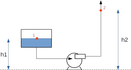
The fluid velocity at condition 1 (liquid surface in tank) is \(0 \text{ m/s}\). At condition 2 inside the \(50 \text{ mm}\) pipe, velocity is:
\[ v_2 = \frac{10 / 3600}{\pi \cdot 0.05^2 / 4} = 1.41 \text{ m/s} \]
Evaluating the total head rise equation:
\[ H = \frac{200000 - 101325}{999 \cdot 9.81} + (5 - 3) + \frac{11.41^2 - 0^2}{2 \cdot 9.81} = 10.07 + 2.00 + 0.10 = 12.17 \text{ m liquid column} \]
Simplification of formula
Note that the example above illustrates all terms of the general equation. However, in most industrial engineering evaluations, the engineer measures pressures across suction and discharge nozzles at identical elevations and identical pipe diameters. The Energy Equation then simplifies to:
\[ H = \frac{P_2 - P_1}{\rho \cdot g} \]
3. Actual head rise calculation
The formulation above calculates the actual differential dynamic head added to the fluid. However, due to hydraulic friction, impeller recirculating losses, and mechanical efficiency, the power input to the pump shaft exceeds the useful hydraulic power transferred to the fluid:
\[ H = H_{\text{shaft}} - H_{\text{loss}} \]
With:
- \(H\) = net actual head gained by fluid (\(\text{m}\))
- \(H_{\text{shaft}}\) = total head equivalent input to pump shaft (\(\text{m}\))
- \(H_{\text{loss}}\) = internal hydraulic friction and turbulence losses inside pump casing (\(\text{m}\))
4. Pump specific work calculation
The pump specific work (\(W\)), defined as the specific energy input per unit mass of liquid (\(\text{J/kg}\)), is directly calculated from total head rise:
\[ W = H \cdot g \]
With:
- \(W\) = specific work of the pump (\(\text{J/kg}\))
- \(H\) = total head rise (\(\text{m}\))
- \(g\) = gravitational acceleration (\(9.81 \text{ m/s}^2\))
💡 Process Plant Engineering Rules of Thumb & Safety Limits
- Suction Line Velocity: Target 0.5 to 1.5 m/s (1.6 to 5.0 ft/s) to minimize frictional pressure drop and prevent cavitation or inadequate Net Positive Suction Head Available (\(\text{NPSHa}\)).
- Discharge Line Velocity: Target 1.5 to 3.0 m/s (5.0 to 10.0 ft/s) for general chemical and process services to balance piping capital cost against pump operating power costs.
- Max Allowable Velocity: Liquid velocities exceeding 4.5 m/s (15 ft/s) can cause erosional wear, water hammer surges, and high pressure losses.
- Elevation Measurements: Always ensure gauge pressures are corrected to the pump centerline elevation reference if pressure transducers are mounted at different heights.
- NPSH Safety Margin: Always ensure \(\text{NPSHa} \ge \text{NPSHr} + 0.6 \text{ m}\) (or 2.0 ft margin) to protect pump impellers against violent vapor bubble collapse.
6. Interactive Online Pump Head Rise Calculator
7. Manufacturers
If you are interested in getting pump characteristics to estimate the head and size of the pump you need for your application, you can contact Pompes Grosclaude: https://www.pompes-grosclaude.com/en/home/
(Note that MyEngineeringTools has no affiliation with this company)
8. Free Excel calculation tool to calculate head rise
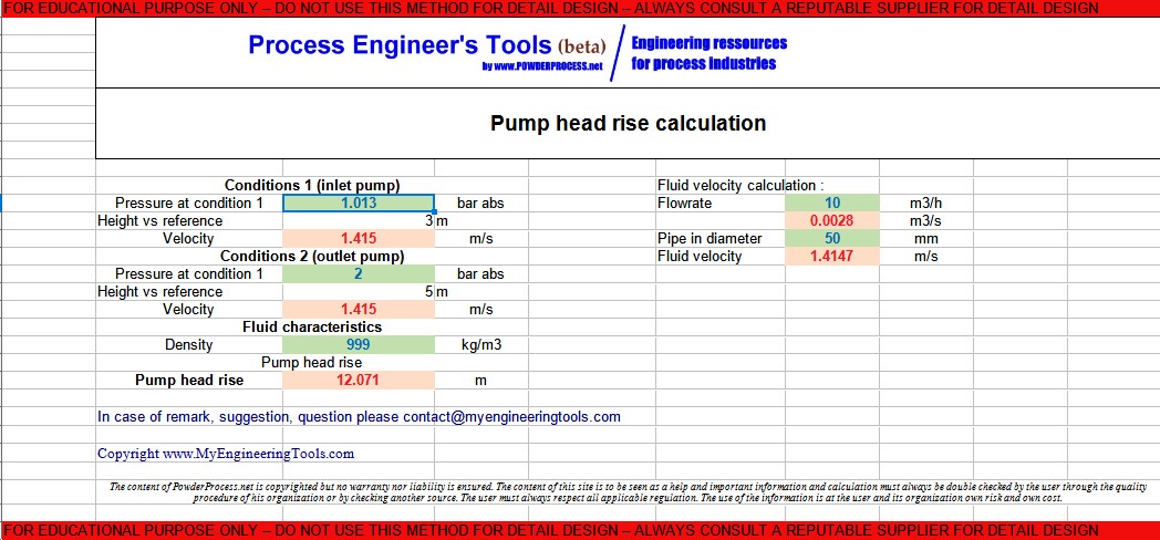
You can access an Excel tool to calculate the head rise of a pump using the exact formulas detailed on this page.
Warning: this calculator is provided to illustrate the concepts mentioned in this webpage, it is not intended for detail design. It is not a commercial product, no guarantee is given on the results. Please consult a reputable designer for all detail design you may need.