
Control valve types
Valve types and typical flow parameters
Follow us on Twitter

Question, remark ? Contact us at contact@myengineeringtools.com
- Globe valves
- Angle valves
- Butterfly Valves
- Gate Valves
- Ball Valves
Interactive Control Valve Sizing & Capacity Calculator
Calculate required \(C_v\) and \(K_v\), evaluate hydrodynamic velocity, verify pressure drop limits, and estimate butterfly valve capacities using the Midoux model.
Calculation Outputs:
This page gives details about the mechanical design and hydrodynamic parameters of the main valve types found in chemical and process industries for control and regulation service. For detailed thermodynamic sizing formulas, please refer to the following companion guides:
- Valve Cv and capacity calculation for liquid and gas flow
- Valve Cv and capacity calculation for steam and superheated steam
- Valve Cv and capacity calculation for laminar flow
Process Engineering Best Practices & Velocity Safety Rules
- Liquid Flow Velocities: Keep valve port velocities below \(4.5\text{ m/s}\) (\(15\text{ ft/s}\)) and adjacent piping liquid velocities between \(1.0 - 2.5\text{ m/s}\) to prevent erosion, line vibration, and water hammer.
- Allowable Sizing Margin: For stable control, size the valve so that normal operating flow corresponds to \(50\% - 70\%\) opening, and maximum flow does not exceed \(85\%\) of maximum rated capacity.
- Cavitation & Flashing Check: Check the liquid pressure recovery factor \(F_L\). The maximum non-choked allowable differential pressure is: \[ \Delta P_{\text{allow}} = F_L^2 (P_1 - P_v) \] If \(\Delta P_{\text{actual}} > \Delta P_{\text{allow}}\), the valve operates in choked/cavitating flow. High-recovery valves (butterfly, ball, \(F_L \sim 0.55 - 0.75\)) are far more prone to cavitation damage than globe valves (\(F_L \sim 0.85 - 0.90\)).
- Equal Percentage vs. Linear: Select equal percentage trims when valve pressure drop varies significantly with flow or constitutes less than \(40\%\) of total system friction. Use linear trims for level control or when valve pressure drop is nearly constant.
1. Globe valves
What is a globe valve ?
Globe valves are among the most popular designs for control valves as they allow fine throttling regulation that cannot be matched by standard butterfly valves, ball valves, or gate valves. The flow between the inlet and outlet is modulated by a moving plug that seals against an internal stationary ring seat.
They are named globe valves because of the globular shape of the cavities within the cast valve body.
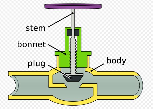
Figure 1 : globe valve [Aimonen]
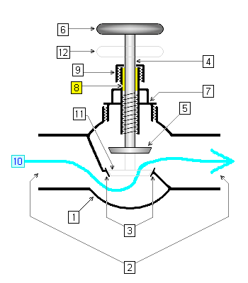
Figure 2 : globe valve [Padleckas]
1. body
2. ports
3. seat
4. stem
5. disc or plug (open position)
6. handle or handwheel
7. bonnet
8. packing
9. gland nut
10. fluid flow (open position)
11. Position of disc when valve is shut
12. Position of handwheel when valve is shut
The plug, cage, seat rings, and internal stems are collectively designated as the valve trim.
The drawings above represent the most common unguided/stem-guided globe valve. An alternative high-performance design utilizes a cylindrical cage inside the body. Lifting the plug within the cage exposes engineered characterized windows (slots or holes) that govern the flow versus lift relationship.
Flow parameters of globe valves
The values below are compiled from the Emerson Fisher Control Valve Handbook and provide typical values for preliminary process sizing:
| Valve size (NPS) | Valve plug type | Flow characteristic | Port diameter (in) | Rated travel (in) | Cv | FL | XT | FD |
|---|---|---|---|---|---|---|---|---|
| 1/2 | Post-Guided | Equal-Percentage | 0.38 | 0.5 | 2.41 | 0.9 | 0.54 | 0.61 |
| 3/4 | Post-Guided | Equal-Percentage | 0.56 | 0.5 | 5.92 | 0.84 | 0.61 | 0.61 |
| 1 | Micro-Form | Equal-Percentage | 3/8 | 3/4 | 3.07 | 0.89 | 0.66 | 0.72 |
| 1 | Micro-Form | Equal-Percentage | 1/2 | 3/4 | 4.91 | 0.93 | 0.8 | 0.67 |
| 1 | Micro-Form | Equal-Percentage | 3/4 | 3/4 | 8.84 | 0.97 | 0.92 | 0.62 |
| 1 | Cage guided | Linear | 1-5/16 | 3/4 | 20.6 | 0.84 | 0.64 | 0.34 |
| 1 | Cage guided | Equal-Percentage | 1-5/16 | 3/4 | 17.2 | 0.88 | 0.67 | 0.38 |
| 1-1/2 | Micro-Form | Equal-Percentage | 3/8 | 3/4 | 3.2 | 0.84 | 0.65 | 0.72 |
| 1-1/2 | Micro-Form | Equal-Percentage | 1/2 | 3/4 | 5.18 | 0.91 | 0.71 | 0.67 |
| 1-1/2 | Micro-Form | Equal-Percentage | 3/4 | 3/4 | 10.2 | 0.92 | 0.8 | 0.62 |
| 1-1/2 | Cage guided | Linear | 1-7/8 | 3/4 | 39.2 | 0.82 | 0.66 | 0.34 |
| 1-1/2 | Cage guided | Equal-Percentage | 1-7/8 | 3/4 | 35.8 | 0.84 | 0.68 | 0.38 |
| 2 | Cage guided | Linear | 2-5/16 | 1-1/8 | 72.9 | 0.77 | 0.64 | 0.33 |
| 2 | Cage guided | Equal-Percentage | 2-5/16 | 1-1/8 | 59.7 | 0.85 | 0.69 | 0.31 |
| 3 | Cage guided | Linear | 3-7/16 | 1-1/2 | 148 | 0.82 | 0.62 | 0.3 |
| 3 | Cage guided | Equal-Percentage | 3-7/16 | 1-1/2 | 136 | 0.82 | 0.68 | 0.32 |
| 4 | Cage guided | Linear | 4-3/8 | 2 | 236 | 0.82 | 0.69 | 0.28 |
| 4 | Cage guided | Equal-Percentage | 4-3/8 | 2 | 224 | 0.82 | 0.72 | 0.28 |
| 6 | Cage guided | Linear | 7 | 2 | 433 | 0.84 | 0.74 | 0.28 |
| 6 | Cage guided | Equal-Percentage | 7 | 2 | 394 | 0.85 | 0.78 | 0.26 |
| 8 | Cage guided | Linear | 8 | 3 | 846 | 0.87 | 0.81 | 0.31 |
| 8 | Cage guided | Equal-Percentage | 8 | 3 | 818 | 0.86 | 0.81 | 0.26 |
Manufacturers of globe valves
For certified quotes, commercial sizing sheets, and pricing, refer to established globe valve manufacturers:
- Guichon valves : http://guichon-vannes.com/
- Sart Von Rohr valves : www.sart-von-rohr.fr
- Gemu valves : gemu-group.com
2. Angle valves
What is an angle valve ?
An angle valve is a specialized variation of a globe valve where the inlet and outlet ports are configured at an angle of \(90^\circ\). This geometry provides an internal self-draining flow path with reduced impingement, making it ideal for slurry services, erosive fluids, coking hydrocarbons, and high pressure drop applications.
3. Butterfly valves
What is a butterfly valve ?
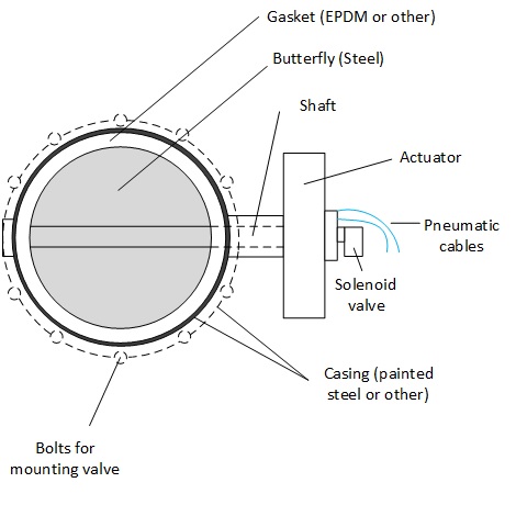
Figure 3 : Butterfly valve
Butterfly valves offer significant advantages in weight, space, and cost compared to globe valves. In the fully open position, they present very low resistance to fluid flow, enabling extremely high flow capacities (\(C_v\)) for compact pipe sizes.
However, standard butterfly valves provide less precise modulation, particularly near the closed position (\(< 20^\circ\) open) where torque dynamics and turbulence are high.
Sealing can be metallic (metal-to-metal, which permits minor leakage according to ANSI Class IV) or resilient elastomeric/PTFE lined for bubble-tight shut-off. In severe services, an eccentric or triple-offset high-performance butterfly valve is used, where the disc shaft is offset from the valve body centerline to eliminate seal rubbing and wear during rotation.
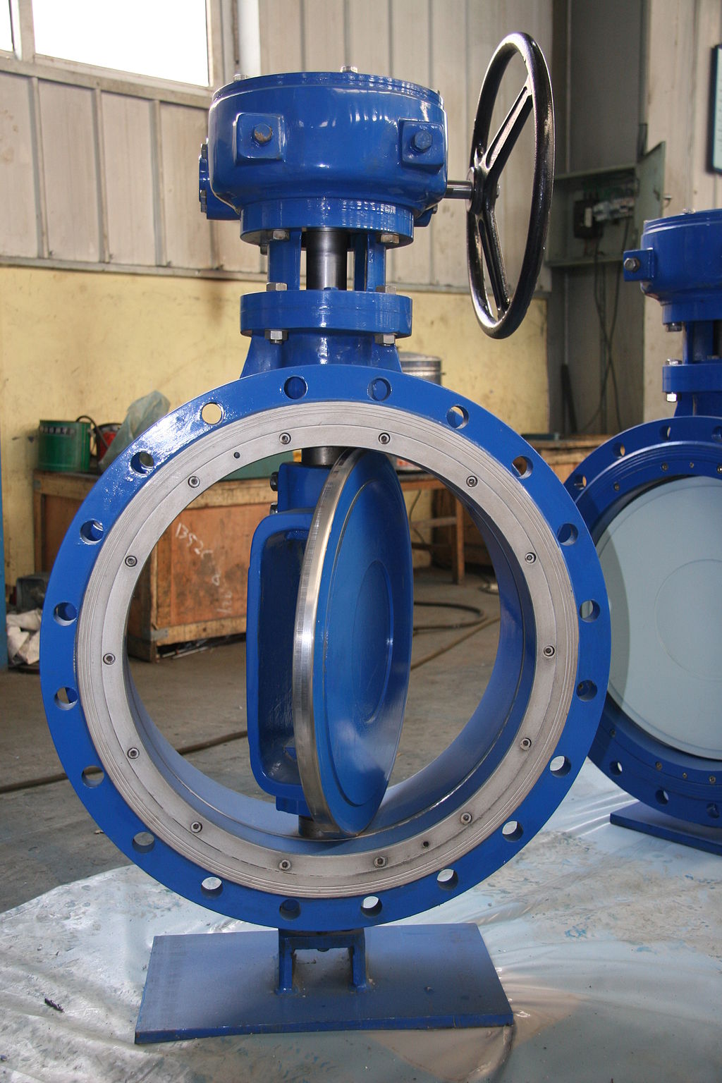
Figure 4 : eccentric butterfly valve
Flow parameters of butterfly valves
The values below are given by Emerson Fisher for standard 60-degree and 90-degree disc openings:
| Valve size (NPS) | Degree of opening | Cv | FL | XT | FD |
|---|---|---|---|---|---|
| 2 | 60 | 58.9 | 0.76 | 0.5 | 0.49 |
| 2 | 90 | 80.2 | 0.71 | 0.44 | 0.7 |
| 3 | 60 | 115 | 0.81 | 0.46 | 0.49 |
| 3 | 90 | 237 | 0.64 | 0.28 | 0.7 |
| 4 | 60 | 270 | 0.69 | 0.32 | 0.49 |
| 4 | 90 | 499 | 0.53 | 0.19 | 0.7 |
| 6 | 60 | 664 | 0.66 | 0.33 | 0.49 |
| 6 | 90 | 1260 | 0.55 | 0.2 | 0.7 |
| 8 | 60 | 1160 | 0.66 | 0.31 | 0.49 |
| 8 | 90 | 2180 | 0.48 | 0.19 | 0.7 |
| 10 | 60 | 1670 | 0.66 | 0.38 | 0.49 |
| 10 | 90 | 3600 | 0.48 | 0.17 | 0.7 |
| 12 | 60 | 2500 | - | - | 0.49 |
| 12 | 90 | 5400 | - | - | 0.7 |
| 16 | 60 | 3870 | 0.69 | 0.4 | - |
| 16 | 90 | 8600 | 0.52 | 0.23 | - |
Midoux Empirical Model for Butterfly Valves
Alternatively, [Midoux] presents the following generalized hydrodynamic relations for butterfly valve capacity:
\[ \frac{C_v}{D_v^2} = 5 \times 10^{-2} \times f^2 \] \[ f = \frac{90 - \theta}{90} \] \[ F_L \approx 0.675 \]Where:
- \(D_v\) = nominal diameter of the valve \([\text{m}]\)
- \(\theta\) = angle of closure / opening \([^\circ]\) (where \(f = 1\) represents the fully open \(90^\circ\) position)
- \(C_v\) is calculated in \([\text{m}^3/\text{s}]\). Multiply by \(1.32 \times 10^6\) to convert to standard US gpm units (\([\text{gpm} / \sqrt{\text{psi}}]\)).
Worked Example (Midoux formula):
For a 4-inch valve (\(D_v = 0.1016\text{ m}\)) at fully open position (\(f = 1\)):
\[ C_v = 5 \times 10^{-2} \times (0.1016)^2 = 5.16 \times 10^{-4} \text{ m}^3/\text{s} \] \[ C_v = 5.16 \times 10^{-4} \times (1.32 \times 10^6) = 681 \text{ gpm} \] \[ F_L = 0.675 \]This theoretical estimate aligns closely with experimental catalog data (NPS 4 catalog \(C_v = 499\), \(F_L = 0.53\)).
Manufacturers of butterfly valves
- Buracco : www.buracco.com
- Robvalve : https://robvalve.wixsite.com/
- ABZ Valves
- Keystone Butterfly Valves (Emerson)
- Nibco Butterfly Valves
4. Gate valves
What is a gate valve ?
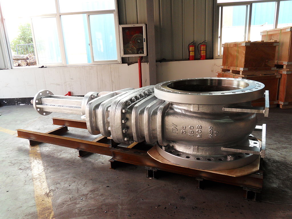
Gate valves are intended strictly for fully open (isolation) or fully closed on/off service. They should not be used as throttling control valves because fluid velocity at partial opening generates severe disc fluttering, gate seat scouring, and chattering vibration.
Manufacturers of gate valves
- UCMA valves : www.ucmasn.fr
- PAM valves : https://www.pamline.fr
5. Ball valves
What is a ball valve ?
In a ball valve, the closing element is a sphere with a central flow bore. Rotating the ball by \(90^\circ\) opens or closes the flow path. Segmented ball valves featuring a notched V-contour (V-notch or V-ball) provide an equal percentage characteristic and high shearing capability for fibrous pulps, slurries, and viscous media.
Flow parameters of ball valves (V-Notch)
The values below are given by Emerson Fisher for typical rotary V-notch control ball valves:
| Valve size (NPS) | Degree of opening | Cv | FL | XT | FD |
|---|---|---|---|---|---|
| 1 | 60 | 15.6 | 0.86 | 0.53 | - |
| 1 | 90 | 34 | 0.86 | 0.42 | - |
| 1-1/2 | 60 | 28.5 | 0.85 | 0.5 | - |
| 1-1/2 | 90 | 77.3 | 0.74 | 0.27 | - |
| 2 | 60 | 59.2 | 0.81 | 0.53 | - |
| 2 | 90 | 132 | 0.77 | 0.41 | - |
| 3 | 60 | 120 | 0.8 | 0.5 | 0.92 |
| 3 | 90 | 321 | 0.74 | 0.3 | 0.99 |
| 4 | 60 | 195 | 0.8 | 0.52 | 0.92 |
| 4 | 90 | 596 | 0.62 | 0.22 | 0.99 |
| 6 | 60 | 340 | 0.8 | 0.52 | 0.91 |
| 6 | 90 | 1100 | 0.58 | 0.2 | 0.99 |
| 8 | 60 | 518 | 0.82 | 0.54 | 0.91 |
| 8 | 90 | 1820 | 0.54 | 0.18 | 0.99 |
| 10 | 60 | 1000 | 0.8 | 0.47 | 0.91 |
| 10 | 90 | 3000 | 0.56 | 0.19 | 0.99 |
| 12 | 60 | 1530 | 0.78 | 0.49 | 0.92 |
| 12 | 90 | 3980 | 0.63 | 0.25 | 0.99 |
| 16 | 60 | 2380 | 0.8 | 0.45 | 0.92 |
| 16 | 90 | 8270 | 0.37 | 0.13 | 1.0 |
Manufacturers of ball valves
- Guichon valves : http://guichon-vannes.com/
- GRK valves : https://www.grk.fr/
Source References
[Aimonen] Globe valve engineering drawing, Wikipedia Creative Commons
[Padleckas] Globe valve cross-section diagram, Wikimedia Commons
[Emerson] Control Valve Handbook, 5th Edition, Emerson Fisher Controls International LLC
[Midoux] Mécanique et Rhéologie des Fluides en Génie des Procédés, page 392, N. Midoux, Lavoisier Tec & Doc