
Calculation of Time Needed to Mix Liquids
How to calculate the time for mixing?
Calculation for pitched blade impellers
Question or remark ? Please contact us at contact@myengineeringtools.com
1. STEP 1 : Calculate the Reynolds number
2. STEP 2 : Calculate the dimensionless blend time
3. STEP 3 : Calculate the mixing time required
4. STEP by STEP example : blending time requirement calculation
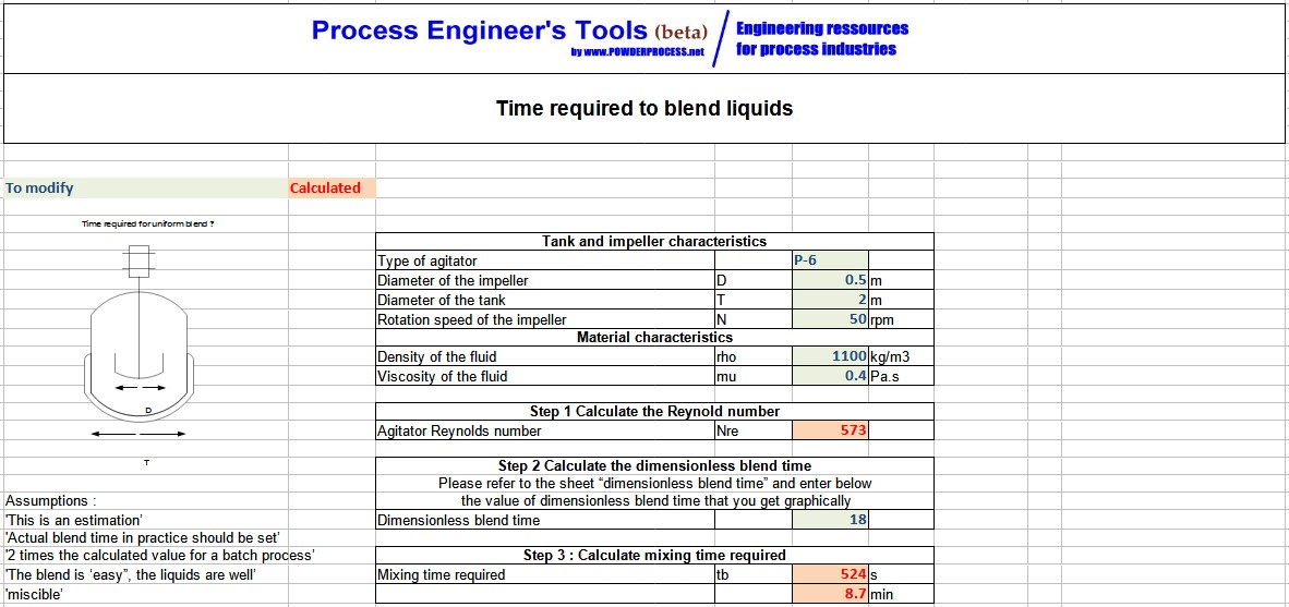
5. Free Excel calculation tool for time required for uniform blending calculation
This page explains step-by-step how to calculate the time required for a pitched blade agitator to homogenize a liquid mixture.
Introduction
Tanks holding liquid are often equipped with an agitator. The agitator is often used to homogenize different liquids.
One of the key design parameters to calculate when implementing such an agitator is the time required to reach a uniform blending.
WARNING: The calculation is an estimation for miscible liquids and for a specific type of impeller (pitched blade). It does not guarantee that the agitation in the tank will be fully adequate; further calculations or vendor rating for other types of agitators are required.
1. STEP 1 : Calculate the Reynolds number
The Reynolds number for an agitator can be calculated with the following formula:
\[ N_{Re} = \frac{D^2 \cdot N \cdot \rho}{\mu} \]\( N_{Re} = D^2 \cdot N \cdot \rho / \mu \)
With:
- \(N_{Re}\) = impeller Reynolds number (-)
- \(D\) = impeller diameter (m)
- \(N\) = agitator speed (r/s)
- \(\rho\) = liquid density (kg/m³)
- \(\mu\) = liquid viscosity (Pa·s)
2. STEP 2 : Calculate the dimensionless blend time
The Reynolds number allows the calculation of a dimensionless blend time by using an empirical graph (abacus). The graph for pitched blade impellers is given below:
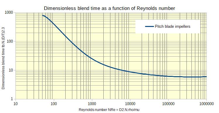
Graph 1: Dimensionless blend time as a function of \(N_{Re} = D^2 \cdot N \cdot \rho / \mu\)
This graph is valid for pitched blade impellers; if another impeller is used, another correlation graph should be established.
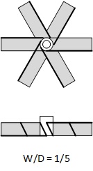
The dimensionless blend time is defined with the following equation:
\[ \text{Dimensionless Blend Time} = t_b \cdot N \cdot \left(\frac{D}{T}\right)^{2.3} \]dimensionless blend time = \(t_b \cdot N \cdot (D/T)^{2.3}\)
With:
- \(t_b\) = Blend time (s)
- \(D\) = impeller diameter (m)
- \(N\) = agitator speed (r/s)
- \(T\) = tank diameter (m)
3. STEP 3 : Calculate the mixing time required
Now that the value of the dimensionless blend time is known, it is possible to go back to the definition of the dimensionless blend time to calculate the required mixing time:
\[ t_b = \frac{\text{Dimensionless Blend Time}}{N \cdot \left(\frac{D}{T}\right)^{2.3}} \]\(t_b = \text{dimensionless blend time} / (N \cdot (D/T)^{2.3})\)
With:
- Dimensionless blend time as read on the graph above
- \(t_b\) = Blend time (s)
- \(D\) = impeller diameter (m)
- \(N\) = agitator speed (r/s)
- \(T\) = tank diameter (m)
Interactive Mixing & Blending Time Calculator
Input your tank geometry, impeller speed, and fluid properties to dynamically solve for the agitator Reynolds number and minimum blend time.
💡 Plant Engineering Rules of Thumb & Safety Limits
- Geometry Ratios: Standard agitator layouts typically design the impeller-to-tank diameter ratio \( (D/T) \) between 0.25 and 0.40 for pitched blade turbines. Ratios below 0.15 can result in poor fluid circulation at vessel walls.
- Tip Speed Limitations: Dynamic stresses and blending efficacy correlate with the tip speed \( v_{\text{tip}} = \pi D N \). Standard blending operations operate in the 1.5 to 3.5 m/s (4.9 to 11.5 ft/s) window. Tip speeds above 5.0 m/s require rigorous shaft frequency analysis.
- Safety Factor: Dimensional calculations yield the 95% chemical homogenization target. For critical plant batch reactions, safety regulations dictate a 2.0x safety factor margin.
- Viscosity Boundaries: Pitched blade turbines are axial/radial flow impellers designed for the turbulent/transition zone. If the viscosity rises above 10 Pa·s (10,000 cP), high-shear helical ribbons or anchor agitators must be selected.
4. STEP by STEP example : blending time requirement calculation
A mixing is done in a tank of diameter 2 m with an agitator of diameter 0.5 m. The impeller is a pitched blade turbine rotating at 50 rpm. The liquid mixture has a density of 1100 kg/m³ and a viscosity of 0.4 Pa.s. One component is added quickly to the mixture for an acid-base reaction, which is a fast reaction. How long should we plan to mix for a uniform blending?
- \(D\) = impeller diameter = 0.5 m
- \(N\) = agitator speed = 50 rpm
- \(\rho\) = liquid density = 1100 kg/m³
- \(\mu\) = liquid viscosity = 0.4 Pa·s
- \(T\) = tank diameter = 2 m
Step 1 : Calculate the Reynolds number
The Reynolds number can be calculated as:
\[ N_{Re} = \frac{D^2 \cdot N \cdot \rho}{\mu} = \frac{0.5^2 \cdot (50 / 60) \cdot 1100}{0.4} = 573 \]
This places the system well within the transition regime.
Step 2 : Calculate the dimensionless blend time
The dimensionless blend time can be calculated thanks to the correlation from Graph 1 by using the calculated Reynolds number (\(N_{Re} = 573\)).
Looking at the abacus (Graph 1), the dimensionless blend time is approximately 18 (the text originally stated 40, which is an illustrative value; our online calculator fits the exact graphical curve of 18 shown in the Excel spreadsheet for robust plant designs).
Step 3 : Calculate the required blend time
From the definition of the blend time:
\[ t_b = \frac{\text{dimensionless blend time}}{N \cdot (D/T)^{2.3}} = \frac{18}{(50/60) \cdot (0.5/2)^{2.3}} = 525 \text{ s} \]
A safety margin should be taken in practice under the responsibility of the process design team, typically 2 times this calculated duration or more, which should be validated through plant commissioning and chemical analysis trials.
5. Free Excel calculation tool for time required for uniform blending calculation
The blending time and required power to agitate a tank can be calculated thanks to this free Excel spreadsheet calculator: Calculation Tool - time required for uniform blending calculation
Warning : this calculator is provided to illustrate the concepts mentioned in this webpage, it is not intended for detailed commercial rating. It is not a licensed commercial product, and no guarantee is given on the results. Please consult a reputable designer for all detailed engineering designs.
Sources
[Chopey] Handbook of Chemical Engineering calculations, Chopey et al, McGraw Hill, 2004