
Reboiler / kettle design : calculation method
Follow us on Twitter 
Question, remark ? Contact us at contact@myengineeringtools.com
| Section summary |
|---|
| 1. Condenser
definition |
| 2. Condenser
calculation procedure |
1. Reboiler definition
What is a reboiler ?
Reboilers, and their subtype kettle reboilers, are used in process industries at the bottom of the distillation columns. They are used to vaporize part of the liquid collected at the bottom of the column and thus constitute an important equipment to run the distillation process. They are typically designed like a shell-tube heat exchanger but a change of state is happening on the shell side as part of the liquid is turned into vapor.
At the bottom of the distillation column, part of the liquid is sent to the reboiler, part of the liquid is diverted to the next process step. The reboiler is then vaporizing the liquid recirculated and release it back to the distillation column. The liquid can be pumped to the reboiler (forced recirculation) or can be directly naturally to the reboiler (thermosyphon).
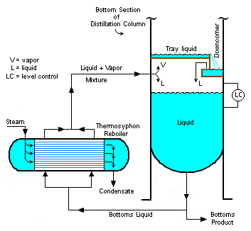
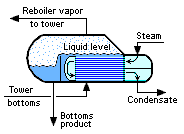
It is possible to avoid the split of the liquid flow, at the bottom of the column, by using a special reboiler, called kettle reboiler, whose shell is actually equipped with an overflow plate. The liquid can only acummulate to the level of the plate, and all overflowing liquid is discharged. The tubes circulating the heating media are positionned below the maximum liquid level so that they can be heat up and vaporize efficiently the liquid.
2. Calculation procedure : reboiler sizing
How to design a shell-tube reboiler ?
2.1 STEP 1 : get the design data
The following data must be defined in order to check the design, or size a condenser :
- Fluid properties (viscosity, specific heat, latent heat for the fluid to be condensed... if possible as a function of temperature)
- Inlet and outlet temperature of each fluids (note : the procedure here is to size a heat exchanger knowing those data, but it can be adapted after, using Excel, to calculate the outlet temperature knowing the characteristics of the heat exchanger for example)
- Inlet pressure of fluids
- Allowable pressure drop
It is assumed that the vapor to condensate is in the shell side.
2.2 STEP 2 : calculate the required heat flux
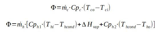
The heat flux can be calculated knowing the flowrate, the in and out temperatures, the specific heat of the fluid, and the latent heat of the fluid to boil. In many cases, steam is used as the heating fluid, and steam is condensated in the process in order to recover the latent heat of vaporization.
If possible, it is easier to calculate the heat flux on the hot side as there is normally no phase change.
With
mc = mass flowrate on cold side (kg/s)
Cpc = specific heat of cold fluid
Tco = outlet temperature of cold side (K)
Tci = inlet temperature of cold fluid (K)
mh = mass flowrate of vapor to condense on hot side
(kg/s)
Cph1 = specific heat of vapor (J/kg/K)
Thi = inlet temperature of vapor to condense (K)
Thcond = condensation temperature of the pure vapor (K)
ΔHvap = latent heat of vaporization of the pure sustance
(J/kg/K)
Cph2 = specific heat condensed liquid (J/kg/K)
Tho = outlet temperature of hot side (K)
It is then possible to approximate the size of the heat exchanger by estimating the overall heat transfer coefficient H.
H for reboilers is often in between 75 to 750 kcal/h.m2.c = 0.087 to 0.87 kW/m2.K.
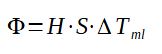
H = overall heat exchange coefficient (kW/m2.K)
S = area of the heat exchanger (m2)
ΔTml
(K)
The value of S can thus be calculated, as a 1st approximation of the heat exchanger size.
2.3 STEP 3 : define a tentative geometry
At this stage, assume a geometry (number of tube, diameter of tube,
diameter of shell) reaching the surface area required. If you have a
manufacturer brochure, you can refer to it.2.4 STEP 4 : Calculation of the heat exchange coefficient on the tube side
It is assumed that the heating fluid, thus the fluid that is not submitted to a change of state, is located in the tubes. As a consequence, a general relation correlating the Nusselt number to the Reynolds and Prandtl number can be used for assessing the heat transfer coefficient :
Nu = (htube.di)/λc
With :
Nu = Nusselt number, calculated by the correlations below
htube = heat transfer coefficient on tube side (W.m-2.K-1)
λc = thermal conductivity of the cooling fluid (W/(m.K))
(m⋅kg⋅s−3⋅K−1)
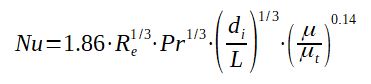
2.4.1 Laminar flow (Re < 2100)
The following correlation is from Sieder and Tate
Nu = 1.86.Re1/3.Pr1/3.(di / L)1/3.(μ/μt)0.14
With :
Re = Reynolds number
Pr = Prandtl number = Cp.μ / λ
di = internal diameter of the tube in m
L = length of the tube in m
μ = viscosity of the fluid at bulk temperature in Pa.s (kg/m/s)
μt = viscosity of the fluid a wall temperature in Pa.s
(kg/m/s) - please refer to paragraph 2.6.1 for the calculation of Twall
Cp = specific heat of the fluid in J/kg/K (m2/s2/K)
λ = thermal conductivity of the fluid (W/(m.K)) (m⋅kg⋅s−3⋅K−1)
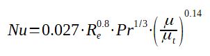
2.4.2 Turbulent flow (Re > 10000)
The following correlation is from Colburn.
Nu = 0.027.Re0.8.Pr1/3.(μ/μt)0.14
2.4.3 Calculation of Reynold number
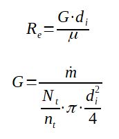
The Reynolds number can be calculated as a function of the mass flow, number of tubes, number of passes, tube diameter.
Re = G.di / μ
G = m / [(Nt/nt).π.di2/4]
With
G = mass flux in the tube in kg/s/m2
ṁ = mass flow in the heat exchanger on the tube side in kg/s
Nt = number of tubes in the shell tube heat exchanger
nt = number of passes tube in the shell tube heat
exchanger
μ = viscosity of the fluid at bulk temperature in Pa.s (kg/m/s)
2.5 STEP 5 : Calculation of the heat exchange coefficient on the shell side
It is assumed that the liquid is already at saturation and ready to boil, if it is required to heat up to ebulition, additional exchange area is required.
2.5.1 Reynolds calculation
Vertical tubes
The Reynolds number is, for the liquid condensate, expressed as :
Re = (4*Gv) / μ
With :
Re = Reynolds number (-)
Gv = mass flowrate of condensate per unit of length of
tube (kg/s/m) = mc / (π*do*Nt)
μ = viscosity of the condensate (Pa.s) - please refer to paragraph
2.6.1 for the calculation of Tfilm
mc = mass flowrate of vapor (= condensate if all the
vapor is condensed) (kg/s)
do = tube outside diameter (m)
Nt = number of tubes in the shell (-)
Horizontal tubes
The Reynolds number is, for the liquid condensate, expressed as :
Re = (4*Gh) / μ
With :
Re = Reynolds number (-)
Gh = mass flowrate of condensate per unit of length of
tube (kg/s/m) = mc / (L*Nt1/4)
μ = viscosity of the condensate (Pa.s) - please refer to paragraph
2.6.1 for the calculation of Tfilm
mc = mass flowrate of vapor (= condensate if all the
vapor is condensed) (kg/s)
L = tube length (m)
Nt = number of tubes in the shell (-)
To be noted that, for horizontal condensers, the flow regime of the condensate in the shell is actually laminar, the calculation above is thus not really necessary
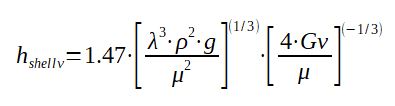
2.5.2 Laminar flow (Re < 2100)
Vertical tubes
The heat transfer coefficient on the shell side, for vertical tubes, with the condensate in laminar flow can be expressed as :
hshell = hshellv = 1.47*[λ3*ρ2*g/μ2]1/3[(4*Gv) / μ]-1/3
With
hshellv = heat exchange coefficient on the shell side
for vertical tubes (W.m-2.K-1)
λ = thermal conductivity of the condensate fluid (W/(m.K)) (m⋅kg⋅s−3⋅K−1)
- please refer to paragraph 2.6.1 for the calculation of Tfilm
ρ = density of the condensate fluid (kg/m3)
g = 9.81 m.s-2
μ = viscosity of the condensate (Pa.s) - please refer to paragraph
2.6.1 for the calculation of Tfilm
Gv = mass flowrate of condensate per unit of length of
tube (kg/s/m) = mc / (π*do*Nt)
Horizontal tubes
hshell = hshellh = 1.51*[λ3*ρ2*g/μ2]1/3[(4*Gh) / μ]-1/3
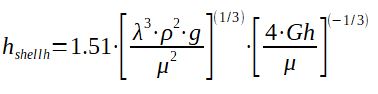
With
hshellh = heat exchange coefficient on the shell side
for horizontal tubes (W.m-2.K-1)
λ = thermal conductivity of the condensate fluid (W/(m.K)) (m⋅kg⋅s−3⋅K−1)
- please refer to paragraph 2.6.1 for the calculation of Tfilm
ρ = density of the condensate fluid (kg/m3) - please refer to
paragraph 2.6.1 for the calculation of Tfilm
g = 9.81 m.s-2
μ = viscosity of the condensate (Pa.s) - please refer to paragraph
2.6.1 for the calculation of Tfilm
Gh = mass flowrate of condensate per unit of length of
tube (kg/s/m) = mc / (L*Nt)
2.5.3 Turbulent flow (Re < 10000)
Vertical tubes
hshell = hshellv = 0.0076*[λ3*ρ2*g/μ2]1/3[(4*Gv) / μ]0.4
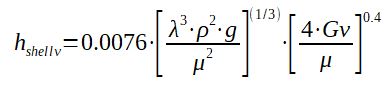
With
hshellv = heat exchange coefficient on the shell side
for vertical tubes (W.m-2.K-1)
λ = thermal conductivity of the condensate fluid (W/(m.K)) (m⋅kg⋅s−3⋅K−1)
- please refer to paragraph 2.6.1 for the calculation of Tfilm
ρ = density of the condensate fluid (kg/m3) - please refer to
paragraph 2.6.1 for the calculation of Tfilm
g = 9.81 m.s-2
μ = viscosity of the condensate (Pa.s) - please refer to paragraph
2.6.1 for the calculation of Tfilm
Gv = mass flowrate of condensate per unit of length of
tube (kg/s/m) = mc / (π*do*Nt)
2.6 STEP 6 : calculation of the actual overall heat transfer coefficient Hcalculated
The heat transfer coefficient is the sum of the convection inside the tube, the conduction through the tubes, the convection outside the tube, also considering the fouling resistances on both sides of the tube. The actual overall heat transfer coefficient is thus :

Hcalculated = overall heat transfer coefficient (W.m-2.K-1)
htube = heat transfer coefficient on tube side (W.m-2.K-1)
Rtube = fouling resistance on tube side (K.W-1.m-2)
hshell = heat transfer coefficient on shell side (W.m-2.K-1)
Rshell = fouling resistance on shell side (K.W-1.m-2)
di = tube inside diameter (m)
do = tube outside diameter (m)
λm = thermal conductivity of the material of the tubes
(W.m-1.K-1)
2.6.1 Calculation of the film temperature
In order to calculate properly the overall heat exchange temperature, it is required to know what is the actual temperature of the condensing liquid on the tube where the liquid is making a thin film. In order to approximate this temperature, the following calculation can be done :
Tfilm = (Thcond+Twall)/2
With :
Tfilm = temperature of the film of condensed liquid on
the tube (K)
Thcond = temperature of the vapor = condensation
temperature of the vapor (K)
Twall = wall temperature of the tube (K)
The temperature Twall of the tube can be calculated by :
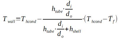
With :
Thcond = temperature of the vapor = condensation
temperature of the vapor (K)
Twall = wall temperature of the tube (K)
htube = heat transfer coefficient on tube side (W.m-2.K-1)
hshell = heat transfer coefficient on shell side (W.m-2.K-1)
di = tube inside diameter (m)
do = tube outside diameter (m)
Tf = average temperature of the cooling fluid (K) = (Tci+Tco)/2
Tco = outlet temperature of cold side (K)
Tci = inlet temperature of cold fluid (K)
It is actually an iterative process. Indeed, at the beginning of the calculation the film temperature is not known. To get a 1st approximation and start the calculation it can be assumed for example that htube = hshell. The procedure is then :
- Assume htube = hshell
- Calculate Twall and Tfilm
- Calculate hshell and htube
- Recalculate Twall and Tfilm
- If Twall_step2 = Twall_step4 AND Tfilm_step2 = Tfilm_step4, then go to step 6, if not return to step 2
- Calculate the overall heat transfer coefficient Hcalculated
2.6.2 Verify that the the available heat transfer is sufficient
It is then required to compare H calculated with H assumed.
If Hcalculated = Hassumed, the calculation is valid, the size of the heat exchanger, with the total heat exchange area S is correct.
If Hcalculated ≠ Hassumed, then the calculation needs to be run again, this time using Hassumed as starting point, or, if values are really far, changing the design of the heat exchanger size / design and running it again.
2.7 STEP 7 : Calculation of the pressure drop
The design defined in step 6 is only valid if the pressure drop on both sides is less than the allowable pressure drop. If yes, the design can be kept, if not, some design choices such as the size of the tube, number of tubes... On the tube side, the pressure drop can be calculated with the same formula as for a standard shell tube heat exchanger.
On the shell side, the vapor pressure drop is usually very low.
2.8 STEP 8 : optimization and detail design
Even if the design done satisfies the process conditions, it may be possible to improve the design by making it less costly, more compact... the design procedure can then be re-run for the basic design calculated by changing the number of tubes, diameter of tube, tube length...etc...
The procedure above will be helpful to get an idea but cannot be used to such details. It should be done with a specialized company. Detail design and construction drawing must always be done with the support of such a company.
[H Padleckas] Drawing of kettle reboiler published on Wikipedia