
Centrifugal pump shut-off head : definition, calculation, online calculator
What is the shut-off head of a pump ?
How to calculate the shut off head of a centrifugal pump ?
Follow us on Twitter 
Question, remark ? Contact us at contact@myengineeringtools.com
1. Introduction to Centrifugal Pumps and Shut-Off Head
2. Determining Shut-Off Head
4. Calculation Examples
6. Pump Shut-Off Head Calculator Online
1. Introduction to Centrifugal Pumps and Shut-Off Head
What are centrifugal pumps and what is shut-off head?
Centrifugal pumps are the backbone of fluid handling systems, converting rotational energy into kinetic energy and subsequently into pressure energy. At the heart of every centrifugal pump is the impeller, which accelerates the fluid, imparting high velocity. This fluid then enters the volute—a spiral-shaped casing designed to convert kinetic energy into static pressure, ultimately discharging the fluid into the piping system.
The performance of a centrifugal pump is best understood through its head-flow curve, which plots the relationship between discharge head (pressure) and flow rate. A critical point on this curve is the shut-off head, defined as the maximum head the pump can develop when the discharge is completely closed, resulting in zero flow. Equally important is the best efficiency point (BEP), where the pump operates at its highest efficiency. Deviating too far from the BEP—whether towards shut-off or the maximum flow rate (the "end of curve")—can lead to inefficiencies and potential damage.
Understanding shut-off head is crucial for safe and efficient pump operation. Prolonged operation near shut-off conditions can result in several critical issues:
- Thermal Damage: The mechanical energy converted into heat causes a rapid temperature rise in the trapped fluid, potentially damaging pump components, degrading the fluid, and exceeding the piping system's design temperature.
- Mechanical Stress: High pressure and increased radial and axial thrust at shut-off place significant stress on the impeller, shaft, bearings, and seals, leading to premature wear or failure.
- Hydraulic Instability: The region near shut-off can hide hydraulic instabilities, causing severe vibration and unpredictable performance, despite a seemingly smooth head curve.
Therefore, a thorough understanding of shut-off head, along with its thermal, mechanical, and hydraulic implications, is essential for maintaining system integrity, optimizing energy efficiency, and ensuring pump longevity.
2. Determining Shut-Off Head
How can you determine a centrifugal pump's shut-off head?
While field estimations can provide quick insights, the definitive source for a pump's performance characteristics is always the manufacturer's certified documentation.
2.1. The Manufacturer's Certified Pump Curve
For critical designs, safety calculations, or operational analyses, the manufacturer's certified pump curve is the authoritative data source. This curve provides precise shut-off head values for a specific pump model, impeller trim, and operating speed. Experienced engineers rely on this document, along with associated power and efficiency curves, to make informed decisions.
According to API 610 (12ᵗʰ Edition, Sections 5.1.13–5.1.14 and 6.1.11), pumps must exhibit a stable head–flow curve with continuous rise to shut-off—and when parallel operation is specified, the head rise from rated flow to shut-off must be at least 10 % of the rated differential head. This ensures predictable, controllable load distribution and avoids performance lockout when pumps operate together.
2.2. Field Estimation Method
In the field, shut-off head can be roughly estimated using an empirical formula based on the pump's impeller diameter and rotational speed.
Formula for Shut-Off Head Estimation:
\[ H_{\text{shut-off}} = k \times (D^2) \times \left(\frac{N}{1000}\right)^2 \]Where:
- \( H_{\text{shut-off}} \) = Shut-off head (meters)
- \( k \) = Empirical factor (typically 100-200, average ~140–150)
- \( D \) = Impeller diameter (meters)
- \( N \) = Rotational speed (RPM)
Important Caveats: This formula is a rough rule of thumb and should never replace a certified pump curve for critical calculations. The factor 'k' is not constant; it varies widely depending on the pump's specific speed (\(N_s\)) and hydraulic design (e.g., vane angle, volute design), not just its RPM.
The factor k is based on experience; in order to help the reader, an internet literature overview of the values found for factor k is given below:
| Reference / Rule of Thumb | Original Equation (Imperial) | Converted to SI form H = k·D²·(N/1000)² |
Notes |
|---|---|---|---|
| Engineering ToolBox | h_ft = (d·N / 1840)² |
k ≈ 140 | Works across rpm; derived constant in metres (engineeringtoolbox.com) |
| McNally Institute (60 Hz, 1 800 rpm) | h_ft ≈ d² |
k ≈ 146 | Flat rule for 4-pole motors (mcnallyinstitute.biz) |
| Empowering Pumps cheat-sheet | Same as McNally | k ≈ 146 | Practical ±5 % accuracy (empoweringpumps.com) |
| Cheresources forum (general) | h_ft = (d·N / 1750)² |
k ≈ 138 | Commonly used in O&G sizing (cheresources.com) |
| EngineeringToolBox (alt.) | h_m = 0.00014·D²·N² |
k ≈ 140 | Metric direct form (engineeringtoolbox.com) |
2.3. Theoretical Basis
The empirical formula simplifies complex fluid dynamics principles, such as Bernoulli's equation. A more direct theoretical link exists between head and the square of the impeller tip speed:
\[ H_{\text{ideal}} \approx \frac{U_2^2}{g} = \frac{(\pi \cdot D \cdot N / 60)^2}{g} \]Though this is an idealization for a frictionless pump with zero slip, these principles confirm that head is fundamentally proportional to the square of both the impeller diameter and the rotational speed.
3. Risks and Mitigation of Near Shut-Off Operation
What are the risks of operating a pump near shut-off and how can they be mitigated?
Operating a pump away from its BEP and near shut-off introduces significant risks that must be managed through engineering controls and operational procedures.
3.1. Thermal Risks and Safe Operating Time
At shut-off, nearly all input mechanical shaft power is converted into thermal friction, causing the trapped fluid's temperature to rise rapidly. The time-dependent temperature rise can be calculated to determine a safe operating window before fluid flashing or mechanical seal degradation occurs.
Formula for Temperature Rise:
\[ \Delta T = \frac{P \cdot t}{m \cdot c_p} \]Where:
- \( \Delta T \) = Temperature rise (°C)
- \( P \) = Power absorbed by the fluid (W). Use Brake Horsepower (BHP) at shut-off from the manufacturer's pump curve, not the motor's nameplate power.
- \( t \) = Time of shut-off operation (s)
- \( m \) = Mass of trapped fluid inside the pump casing (kg)
- \( c_p \) = Specific heat capacity of the fluid (J/kg·°C)
To prevent thermal damage, systems often include an automatic minimum flow bypass or continuous recirculation orifice line, ensuring the pump never operates at true zero throughput. For critical services, pump specifications may require validated safe operation at very low flows (e.g., 1% of rated flow).
3.2. Mechanical and Hydraulic Instability
Stable operation at or near shut-off is difficult to predict from the head curve alone. Unstable flow regimes, characterized by high vibration, suction recirculation, and discharge recirculation, typically occur at flow rates from 25% to 60% of the rated flow. Furthermore, API 610 defines the Minimum Continuous Stable Flow (MCSF)—also called the allowable operating region—and mandates that pumps be qualified for reliable operation down to at least 60 % of BEP flow (70 % preferred), safeguarding against hydraulic instability, excessive shaft thrust, bearing fatigue, and seal leakage during low-flow or parallel operation.
Experienced engineers rely on a Factory Acceptance Test (FAT) to define the true Minimum Stable Continuous Flow (MSCF). This involves analyzing not just the head curve, but also power, current, axial thrust, and radial thrust curves across the operating range. Mapping these unstable regions is crucial for defining the safe operating envelope and preventing catastrophic damage during startup, shutdown, or process upsets.
💡 Process Engineering Rules of Thumb & Safety Limits
- Shut-Off Power Rule: Radial centrifugal pumps consume roughly 40% to 60% of rated BEP power at zero flow. Axial flow (propeller) pumps exhibit the reverse behavior—their shut-off power can surge to 200% to 300% of BEP power! Always confirm impeller specific speed (\(N_s\)).
- Critical Safe Operating Time (\(t_{\text{crit}}\)): In standard process water pumps, the water volume trapped inside the casing will reach flash boiling within 2 to 6 minutes at deadhead. Never permit zero flow without an automatic thermal trip or minimum-flow recirculation line.
- Minimum Continuous Stable Flow (MCSF): Standard chemical process pumps typically have an MCSF between 25% and 35% of BEP flow. High-energy hydrocarbon feed pumps (API 610) often demand 60% to 75% of BEP flow to suppress internal stall and suction recirculation.
- Radial Thrust Surge: In single-volute casings, radial load on the impeller peaks precisely at shut-off. This creates maximum shaft deflection, premature mechanical seal face fretting, and drastically reduced L10 bearing life.
4. Calculation Examples
How do you apply formulas to calculate shut-off head and related safety parameters?
The following examples illustrate the application of the principles discussed.
4.1. Example 1: Estimating Shut-Off Head Using Impeller Diameter and RPM
Given:
- Impeller diameter (\( D \)) = 0.3 meters
- Rotational speed (\( N \)) = 1500 RPM
- Empirical factor (\( k \)) = 150
Objective: Provide a rough estimate of the shut-off head (\( H_{\text{shut-off}} \)).
Solution:
\[ H_{\text{shut-off}} = k \times (D^2) \times \left(\frac{N}{1000}\right)^2 \] \[ H_{\text{shut-off}} = 150 \times (0.3^2) \times \left(\frac{1500}{1000}\right)^2 \] \[ H_{\text{shut-off}} = 150 \times 0.09 \times 2.25 = 30.375 \, \text{meters} \]Note: This field estimation should be verified against the manufacturer's certified pump curve before use in operational decisions.
4.2. Example 2: Verifying Pump Operating Conditions
Given:
- Estimated shut-off head = 41.5 meters
- Actual measured operating head (\( H_{\text{actual}} \)) = 28 meters
Objective: Assess if the pump is operating near shut-off.
Analysis: The actual operating head (28 meters) is significantly lower than the shut-off head (41.5 meters), indicating the pump is operating at a flow rate well above shut-off, likely in a stable and efficient region. If the actual head were close to the shut-off head, it would signal a potential issue, such as a closed valve or system blockage, requiring immediate investigation.
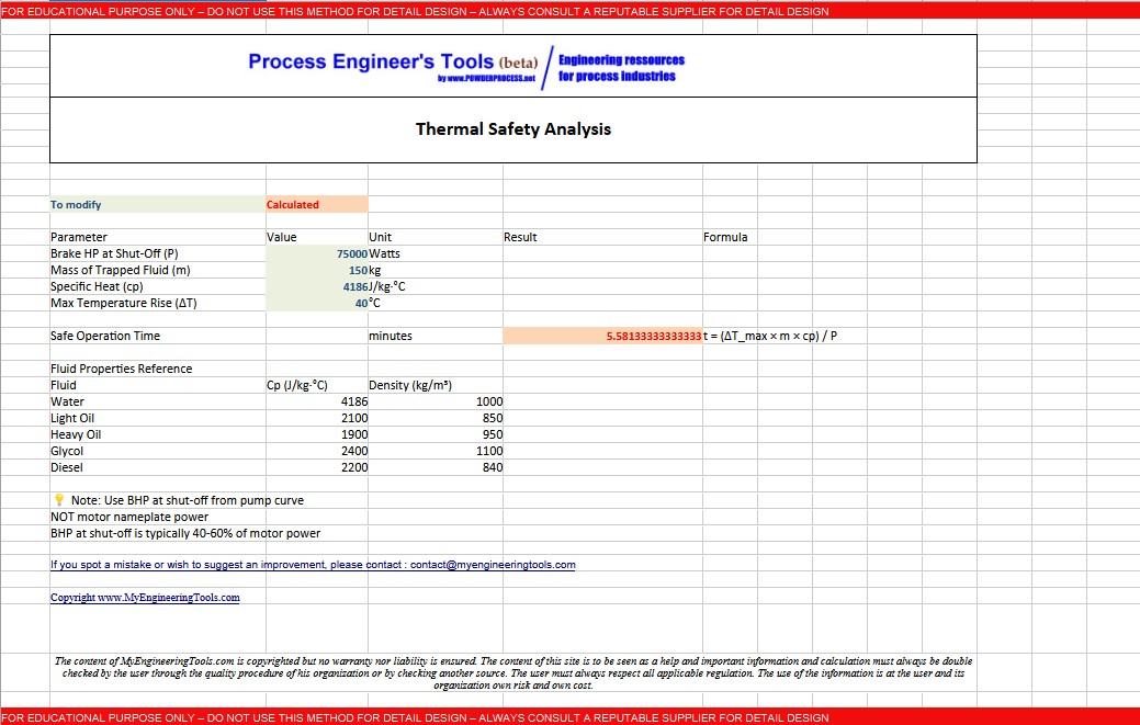
4.3. Example 3: Assessing Safe Operation Time at Shut-Off
Given:
- Brake Horsepower (BHP) at shut-off (\( P \)) = 75,000 W (75 kW)
- Mass of trapped fluid (\( m \)) = 150 kg
- Specific heat capacity of the fluid (\( c_p \)) = 4,186 J/kg·°C
- Maximum allowable temperature rise (\( \Delta T_{\text{max}} \)) = 40°C
Objective: Determine the safe operation time at shut-off based on thermal constraints.
Solution:
Rearrange the temperature rise formula to solve for time (\( t \)):
Note: The safe operation time at shut-off is approximately 5.58 minutes. Automated controls or operator procedures must ensure the pump trips or recirculates before this duration is exceeded.
5. Practical Takeaways
What are the key practical considerations for centrifugal pump shut-off head?
Shut-off head is a critical parameter in centrifugal pump design and operation. While field estimation formulas offer quick insights, they are no substitute for the manufacturer's certified pump curve, which remains the definitive data source.
Operating near shut-off poses significant risks, including rapid fluid overheating, severe mechanical stress, and hydraulic instability. Key takeaways for process engineers include:
- Prioritize Certified Data: Base design and safety decisions on the certified pump performance curve.
- Quantify Thermal Risk: Calculate safe operating time using brake horsepower at shut-off from the pump curve, not the motor's nameplate power.
- Identify the True Safe Envelope: Recognize that a smooth head curve can be misleading. Determine the true Minimum Stable Continuous Flow (MSCF) through comprehensive testing, typically during a Factory Acceptance Test (FAT).
6. Pump Shut-Off Head Calculator Online
Warning : this calculator is provided to illustrate the concepts mentioned in this webpage, it is not intended for detail design. It is not a commercial product, no guarantee is given on the results. Please consult a reputable designer for all detail design you may need.
6.1 Excel (click here to show / hide the calculator)
You can download the calculator here : Download Centrifugal Pump Shut-Off Head Excel Calc
6.2 Online Interactive Calculator (click here to show / hide the calculator)
🔧 Centrifugal Pump Shut-Off Head & Thermal Risk Calculator
📊 Shut-Off Head Estimation
| Parameter | Value | Unit |
|---|---|---|
| Impeller Diameter (D) | m | |
| Rotational Speed (N) | RPM | |
| Empirical Factor (k) | - |
⚠️ K-Factor Guidelines & Benchmarks
| Design / Source | k (SI) | Typical Pump Type |
|---|---|---|
| Cheresources Forum | 138 | General Process / API 610 |
| Engineering ToolBox | 140 | Standard End-Suction ISO/ANSI |
| McNally / Empowering | 146 | 4-Pole Motors (1800 rpm) |
| High Head Impeller | 150–165 | Backward-curved high vane angle |
| Low Specific Speed | 160–200 | Radial flow, steep characteristic |
🌡️ Thermal Safety & Safe Time Analysis
| Parameter | Value | Unit |
|---|---|---|
| Brake Power at Shut-Off (P) | W | |
| Mass of Trapped Fluid (m) | kg | |
| Specific Heat (\(c_p\)) | J/kg·°C | |
| Max Allowable Temp Rise (\(\Delta T\)) | °C |
🔥 Fluid Properties & Thermal Guidelines
| Fluid | \(c_p\) (J/kg·°C) | \(c_p\) (BTU/lb·°F) | Density (kg/m³) |
|---|---|---|---|
| Water (20°C) | 4,186 | 1.00 | 1,000 |
| Light Oil | 2,100 | 0.50 | 850 |
| Heavy Crude | 1,900 | 0.45 | 950 |
| Ethylene Glycol (50%) | 3,300 | 0.79 | 1,070 |
| Diesel Fuel | 2,200 | 0.53 | 840 |
📈 Operating Condition & Margin Analysis
| Parameter | Value | Unit |
|---|---|---|
| Estimated Shut-Off Head (\(H_{\text{so}}\)) | m | |
| Actual Operating Head (\(H_{\text{act}}\)) | m | |
| BEP Head (\(H_{\text{BEP}}\)) | m |
📊 Hydraulic Operating Zone Criteria
| Operating Zone | Head Ratio (\(H/H_{\text{so}}\)) | Mechanical & Process Effects |
|---|---|---|
| Near Shut-Off (<10% Q) | > 90% | High radial thrust, seal heating, cavitation surge |
| Low Flow / MCSF (10–60%) | 80% – 90% | Internal suction/discharge recirculation, vibration |
| Preferred Region (POR) | 65% – 80% | Maximum reliability, lowest vibration, optimal efficiency |
| End of Curve (>120% Q) | < 65% | NPSHr spike, classic cavitation, motor overload risk |
• Theoretical Spouting Tip Head: \( H_{\text{ideal}} = \frac{U_2^2}{g} = \frac{(\pi \cdot D \cdot N / 60)^2}{g} \)
• Transient Thermal Energy Balance: \( \Delta T = \frac{P \cdot t}{m \cdot c_p} \implies t_{\text{safe}} = \frac{\Delta T_{\text{max}} \cdot m \cdot c_p}{P} \)
FAQ: Centrifugal Pumps and Shut-Off Head
1. What is a centrifugal pump?
A centrifugal pump is a fluid handling system that converts rotational energy into kinetic energy and then into pressure energy, using an impeller and a volute casing.
2. What is shut-off head in centrifugal pumps?
Shut-off head is the maximum head a centrifugal pump can develop when the discharge is completely closed, resulting in zero flow.
3. Why is understanding shut-off head important?
Understanding shut-off head is crucial for safe and efficient pump operation, as prolonged operation near shut-off can lead to thermal damage, mechanical stress, and hydraulic instability.
4. How can you determine a pump's shut-off head?
The most reliable source is the manufacturer's certified pump curve, which provides precise shut-off head values for specific pump models and operating conditions.
5. Can shut-off head be estimated in the field?
Yes, using an empirical formula based on the pump's impeller diameter and rotational speed: \( H_{\text{shut-off}} = k \times (D^2) \times \left(\frac{N}{1000}\right)^2 \), where \( k \) is an empirical factor typically between 100-200.
6. What are the risks of operating near shut-off?
Operating near shut-off can cause rapid fluid overheating, severe mechanical stress, and hydraulic instability, potentially leading to pump damage.
7. How can thermal risks at shut-off be mitigated?
Thermal risks can be mitigated by calculating safe operating time using the temperature rise formula: \( \Delta T = \frac{P \cdot t}{m \cdot c_p} \), and ensuring the pump does not exceed this duration.
8. What is the Minimum Continuous Stable Flow (MCSF)?
MCSF is the minimum flow rate at which a pump can operate reliably without hydraulic instability, typically defined as at least 60% of the Best Efficiency Point (BEP) flow.
9. Why is certified pump data essential?
Certified pump data from the manufacturer is essential for accurate design, safety calculations, and operational decisions, as field estimations can be unreliable for critical applications.
10. Where can I find a shut-off head calculator?
You can find a Centrifugal Pump Shut-Off Head Calculator on our website, which includes tools for estimating shut-off head and assessing thermal safety.
Sources
- https://www.eng-tips.com/threads/pump-shut-off-head.110888/
- https://www.scribd.com/document/239701585/SHUT-OFF-HEAD-of-pump
- API Standard 610 / ISO 13709: Centrifugal Pumps for Petroleum, Petrochemical and Natural Gas Industries
- Hydraulic Institute Standards (HI 9.6.1 & HI 9.6.3): Operating Margins and Allowable Operating Regions