
Weir Flow Calculation
Measurement of liquid flowrate in open channels
1. Introduction
2. Rectangular weirs : flow calculation
3. Triangular notch weirs : flow calculation
4. Interactive Online Calculator
1. Introduction
Calculation of flow rate through weirs is particularly interesting in water systems engineering, for the calculation of flow of rivers, dams, sewage systems, and industrial plant effluent streams that have an overflow system that takes the form of a weir.
Different weir geometries are standardly available:
- Rectangular weir (sharp-crested)
- Triangular notch weir (V-notch)
The equations below [Perry] are valid for water flow. With a different fluid, a correction due to the fluid's viscosity and surface tension is required.
Interactive Online Weir Flow Calculator
2. Rectangular weir : flow calculation
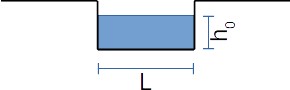
The flow capacity through a rectangular weir is given by the following formula, which applies to sharp-edged rectangular weirs under free discharge conditions:
\[ Q = 0.415 \cdot (L - 0.2 \cdot h_0) \cdot h_0^{1.5} \cdot \sqrt{2 \cdot g} \]With :
\( Q \) = volume flow rate (\( \text{m}^3/\text{s} \))
\( L \) = crest length (\( \text{m} \))
\( h_0 \) = weir head above crest level (\( \text{m} \))
\( g \) = gravitational acceleration = \( 9.81 \text{ m/s}^2 \)
In case \( h_0 > L \), a modification of the calculation formula must be considered as the flow contracts into a narrow channel configuration:
\[ Q = 0.386 \cdot L \cdot h_0^{1.5} \cdot \sqrt{2 \cdot g} \]3. Triangular notch weir : flow calculation

The flowrate that can be achieved through a triangular notch weir (also called V-notch weir), sharp edged, is calculated with the following equation:
\[ Q = \frac{0.31 \cdot h_0^{2.5} \cdot \sqrt{2 \cdot g}}{\tan \Phi} \]Where \( \Phi \) represents the half-angle of the V-notch (e.g., \( \Phi = 45^\circ \) for a standard \( 90^\circ \) V-notch weir).
💡 Practical Engineering Rules of Thumb & Safety Guidelines
- Minimum Head Requirement: To avoid nappe sticking (clinging flow due to surface tension), keep the minimum head \( h_0 \ge 0.03\text{ m} \) (\(1.2\text{ in}\)).
- Aeration/Nappe Ventilation: Always ensure the area under the overflowing water sheet (nappe) is fully aerated at atmospheric pressure. Lack of ventilation creates a partial vacuum that inflates flow rates unpredictably.
- Approach Velocity: The channel upstream must be sufficiently wide and deep so that the approach velocity is below \(0.15\text{ m/s}\), rendering kinetic head negligible.
- Crest Sharpness: Sharp-crested plates should have an edge thickness between \(1\text{ mm}\) and \(2\text{ mm}\) with a downstream bevel angle of \(45^\circ\). Rounding or corrosion on the edge will cause overestimation of discharge capacity.
[Perry] Perry's Chemical Engineer's Handbook, Section 10 Transport and storage of fluids, page 10-24, McGraw-Hill, 2008